PREPARATION
(Item Nos. Refer to Parts list)
10
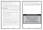
The Headstock is further
secured to the bed by a
clamp (see fig. 2). The clamp
should be firmly applied
using the Handle (item 24A),
and the headstock should
then be solid with the bed.
WARNING: If there is any
movement of the
headstock whatsoever
when the clamp is
tightened, DO NOT start
the machine. Refer to
the Maintenance
section for adjustments.
A. The Headstock
(see fig.2)
To protect the motor during transit, the headstock is rotated and locked at 90
degrees from its normal position, i.e. with the motor over the lathe bed. Pull out the
Headstock Locking Pin (item 35, and see Fig. 7), against spring pressure, allowing
the Headstock to be rotated through 90 degrees so that the spindle faces the
tailstock. Release the locking pin which will reassert itself locking the headstock in
the “in line” position.
The Headstock Spindle is provided with an internal No. 2 Morse Taper, which will
accommodate a suitably tapered centre, and on to which the workpiece may
be mounted. One ‘Live Centre’ is provided which is mounted by simply inserting it
into the spindle. Refer to “Turning between Centres” for further information.
To remove the Live Centre, insert a suitable piece of round bar into the back of the
spindle until it comes into contact with the centre. Give the bar a sharp blow, and
the centre will disengage.
B. The Tailstock
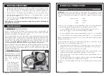
The tailstock is held firm to the
bed by means of a clamp
(see fig 3). Turning the clamp
lever (item 50) anticlockwise,
by approx. one third of a turn,
should release the tailstock,
allowing it to slide along the
bed to the desired position,
and turning the lever back
again should firmly lock the
tailstock in that position.
Fig. 3
Fig. 2
If the tailstock fails to move when the clamp is released, or fails to lock when the
clamp lever is turned clockwise through approx. one third of a turn, the tailstock
securing nut, beneath the tailstock (item 44), is either too loose or too tight.
Adjust the nut so that with the clamp lever turning through approx one third of a
turn, the tailstock slides freely when unclamped, but is held firmly when clamped.
The Tailstock Spindle is provided with an internal No. 2 Morse Taper, and a Morse
tapered centre is provided for ‘between centres’ turning, but any No. 2 Morse
Taper tool, such as a drill chuck, may be mounted and used when required.
To mount a tool in the spindle, ensure the spindle clamp (item 37) is not applied,
then turn the spindle feed handle (item 49) clockwise, thereby extending the
spindle until the tools’ Morse Tapered shank can be inserted to its full length,
locking it into place.
To remove a tool from the tailstock, first slacken off the spindle clamp, allowing the
spindle feed handle (item 49) to be turned anticlockwise, thereby withdrawing
the tool from the workpiece.
Unclamp the tailstock and move it well away from the workpiece. Continue to turn
the spindle feed handle anticlockwise until resistance is felt. At this point, back off
slightly, and then turn the handle sharply, thereby breaking the seal between the
Morse tapered tool and the spindle, allowing the tool to be removed.
Support the tool during this operation, to prevent the possibility of it dropping on to
the lathe bed when it becomes detached.
C. Tool Rest Adjustment
11
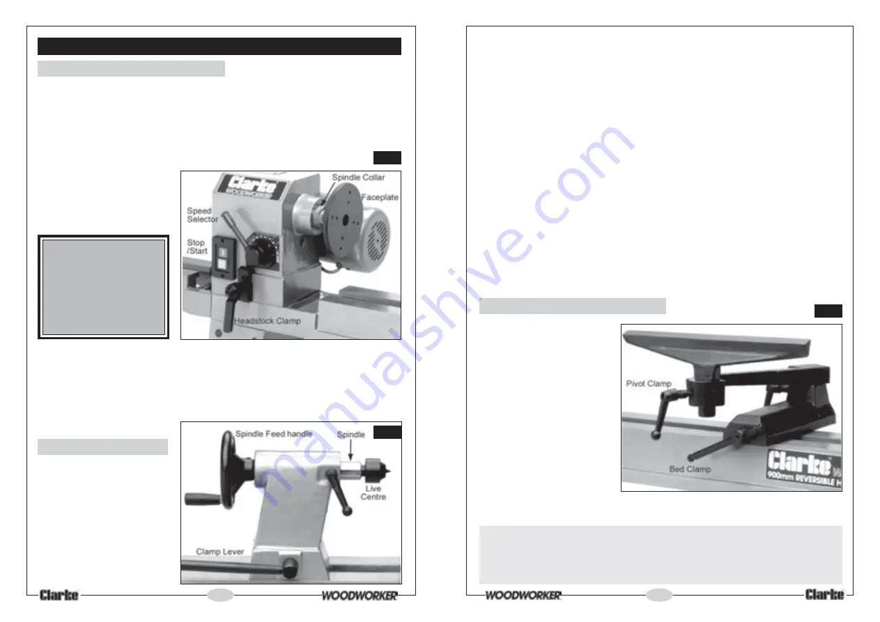
The tool rest is adjustable to
almost any position, using a
combination of pivots and
clamps. The Bed Clamp
(items 41 to 44), when
slackened, allows the tool
rest to slide along the bed to
its desired position and is
adjusted in a similar manner
to the Tailstock Clamp. i.e.
One third of a turn should
clamp or unclamp the
toolrest.
The Tool Rest should always
be on the centre line, and as
close as possible, to the workpiece, but for correct positioning, depending upon
the work being undertaken, consult a wood turning manual
.
IMPORTANT:
Always ensure the Tool Rest clamps are firmly applied, as there is a danger
that the tool rest could swing into the rotating workpiece, with drastic
consequences.
Fig. 4


