background image

ENGLISH

Operator’s Manual - Vantage 13

17

VACUUM GRID, DETERGENT TANK AND RECOVERY TANK CLEANING

Drive the machine to the appointed disposal area.

1. 

Make sure that the power supply cable (10) is disconnected from the electrical mains.

2. 

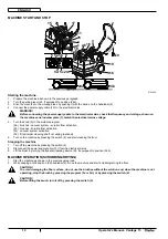
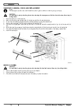
Open the transparent cover (A, Fig. 4) and clean it carefully.

3. 

Clean the vacuum grid (B) with care. If necessary disconnect the hoses (20 and 21).
Check the transparent cover gasket (C) for integrity.

4. 

NOTE

The gasket (C) creates vacuum in the tank that is necessary for vacuuming the recovery water.

If necessary replace the gasket (C) by removing it from its housing (A).
Check that the seating surface (D) of the gasket (C) is integral and adequate for the gasket itself.

5. 

Drain and wash the recovery tank (16) and the detergent tank (14) as shown in Use chapter.

6. 

Install the tanks and the transparent cover with the vacuum grid.

7. 

A

B

D

C

Figure 4

P100315

SOLUTION HOSE FILTER CLEANING

Drive the machine on a level ground.

1. 

Make sure that the power supply cable (10) is disconnected from the electrical mains.

2. 

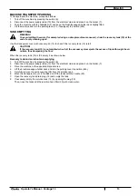
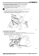
Remove the solution hose plug (A, Fig. 5), carefully remove the hose from the tank and clean the 

fi

 lter (B) with water.

3. 

If necessary, remove the 

fi

 lter and replace it with a new one.

Install the 

fi

 lter and the solution hose in the tank, then install the plug.

4. 

A

B

Figure 5

P100316

Summary of Contents for Vantage 13

Page 1: ...Operator s Manual Libro de Instrucciones Manuel d utilisation READ THIS BOOK LEA ESTE MANUAL LISEZ CE MANUEL EN ES FR English 1 18 Espa ol 19 36 Fran ais 37 54 13 Vantage Form No 9097888000 05 2009...

Page 2: ......

Page 3: ...NG INSTRUCTIONS 6 MACHINE DESCRIPTION 7 MACHINE STRUCTURE 7 ACCESSORIES OPTIONS 8 TECHNICAL DATA 8 WIRING DIAGRAM 9 USE 10 BEFORE MACHINE START UP 10 MACHINE START AND STOP 12 MACHINE OPERATION SCRUBB...

Page 4: ...Clarke will not be answerable for damages coming from the non observance of this prohibition HOW TO KEEP THIS MANUAL The Operator s Manual must be kept near the machine inside an adequate case away f...

Page 5: ...erson responsible for the machine operation Most of the accidents that may occur in a factory while working or moving around are caused by failure to comply with the simplest rules for exercising prud...

Page 6: ...cable never use the power supply cable as a handle Do not close a door on the supply cable or pull the supply cable around sharp edges or corners Do not run the machine on the supply cable The brushes...

Page 7: ...only brushes supplied with the machine and those specified in the Operator s Manual Using other brooms could reduce safety In case of machine malfunctions ensure that these are not caused by a lack of...

Page 8: ...If it will not fit the outlet have a proper outlet installed by a qualified electrician This appliance is for use on a nominal 120 V circuit and has a grounding plug that looks like the plug B Fig 1 A...

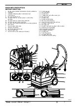
Page 9: ...axle 8 Brush squeegee holder deck 9 Power supply cable 10 Solution hose quick coupling to the pump 11 Front squeegee 12 Rear squeegee 13 Solution tank 14 Transparent cover with vacuum grid 15 Recover...

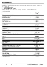
Page 10: ...mm Central wheel diameter 7 in 180 mm Brush diameter 6 5 in 165 mm Brush number No 2 brushes pads Squeegee system Fixed on deck Straight squeegee width 15 in 385 mm Squeegee blades type Front Rear PU...

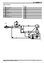
Page 11: ...enser C2 Filtering condenser D1 Pump diode ES1 Relay M1 Brush motor M2 Vacuum system motor P Water pump PL Plug SW1 Main switch SW2 Program selection knob Color code BK Black BU Blue BN Brown GN Green...

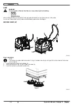
Page 12: ...plates Do not cover these plates for any reason and immediately replace them if damaged BEFORE START UP 1 2 9 3 9 12 18 14 P100308 Brush installation NOTE The machine is supplied with two brushes A F...

Page 13: ...the tank 14 with a solution suitable for the work to be performed 4 Do not fill the solution tank completely leave few inches from the edge Always follow the dilution instructions on the label of the...

Page 14: ...activation 5a brushes solution flow activation 5b vacuum system activation 5c fitted carpet cleaning and floor wiping optional 5d Turn on the machine by pressing the switch 6 and start cleaning the fl...

Page 15: ...is full CAUTION If the recovery tank 16 is not emptied when full the vacuum system ejects the excess of liquid through the air outlets thus dampening the floor When the recovery tank 16 is full empty...

Page 16: ...e previous paragraph 3 Perform the daily maintenance procedures see the Maintenance chapter 4 Store the machine in a clean and dry place 5 MACHINE LONG INACTIVITY If the machine is not going to be use...

Page 17: ...r extraordinary maintenance procedures must be performed by qualified personnel or by an authorized Service Center This Manual describes only the easiest and most common maintenance procedures NOTE Fo...

Page 18: ...by pressing the fasteners 27 4 Check the brush squeegee holder deck 9 and clean it in particular clean the compartments A Fig 3 and the vacuum hole 5 B Wash and clean the squeegee In particular clean...

Page 19: ...sket C by removing it from its housing A Check that the seating surface D of the gasket C is integral and adequate for the gasket itself 5 Drain and wash the recovery tank 16 and the detergent tank 14...

Page 20: ...The brushes do not turn The driving belt is loosened or broken Adjust or replace The brush motor is damaged Replace The squeegee leaves marks on the floor There are debris under the squeegee blades Re...

Page 21: ...MANUAL 20 DATOS DE IDENTIFICACI N 20 OTROS MANUALES DE REFERENCIA 20 PIEZAS DE REPUESTO Y MANTENIMIENTO 20 MODIFICACIONES Y MEJORAS 20 CARACTER STICAS DE FUNCIONAMIENTO 21 CONVENCIONES 21 DESEMBALAJE...

Page 22: ...calificados Clarke no es responsable para los da os causados a la m quina por falta de observaci n de esta prohibici n CONSERVACI N DEL MANUAL Este Manual de uso debe conservarse junto a la m quina de...

Page 23: ...es resulta eficaz sin la total cooperaci n de la persona directamente responsable del funcionamiento de la m quina La mayor a de los accidentes que pueden ocurrir en una empresa durante el trabajo o l...

Page 24: ...e sustituirlo No tirar o transportar la m quina por el cable no usar el cable como empu adura No cerrar el cable en una puerta o tirarlo sobre bordes o ngulos afilados No atropellar el cable con la m...

Page 25: ...n la m quina y aquellos especificados en las Instrucciones de uso Usar otros cepillos puede perjudicar la seguridad Cuando la m quina no funciona correctamente asegurarse de que sto no sea causado por...

Page 26: ...la toma de corriente contactar con un electricista para la instalaci n de una toma adecuada Esta m quina debe funcionar en un circuito de potencia nominal de 120 V y tiene un enchufe semejante al enc...

Page 27: ...e la 11 soluci n detergente a la bomba Boquilla delantera 12 Boquilla trasera 13 Dep sito del detergente 14 Tapa transparente con rejilla de aspiraci n 15 Dep sito del agua de recuperaci n 16 Tubo de...

Page 28: ...2 cepillos fieltros Sistema boquilla Fijo en el cabezal Anchura de la boquilla recta 15 in 385 mm Tipo de cauchos de la boquilla Delantero Trasero PU 65 SH Presi n ruedas sobre el suelo 101 psi 0 7 N...

Page 29: ...rado D1 Diodo para bomba ES1 Rel M1 Motor del cepillo M2 Motor del sistema de aspiraci n P Bomba del agua PL Enchufe de red SW1 Interruptor principal SW2 Perilla de selecci n del programa C digos colo...

Page 30: ...stas placas deben cubrirse y si est n da adas tienen que sustituirse de inmediato ANTES DE LA PUESTA EN MARCHA DE LA M QUINA 1 2 9 3 9 12 18 14 P100308 Instalaci n del cepillo NOTA La m quina se sumin...

Page 31: ...ep sito 14 con una soluci n detergente adecuada 4 No llenar completamente el dep sito del detergente dejar unos cent metros del borde Seguir siempre las instrucciones indicadas en la etiqueta para la...

Page 32: ...uci n detergente 5a accionamiento cepillos apertura flujo soluci n detergente 5b accionamiento del sistema de aspiraci n 5c lavado moqueta y limpiapavimentos opcional 5d Poner en marcha la m quina pul...

Page 33: ...gua de recuperaci n 16 est lleno el sistema de aspiraci n expulsa el exceso de l quido a trav s de los orificios de salida del aire mojando el suelo Cuando el dep sito del agua de recuperaci n 16 est...

Page 34: ...pu s de la utilizaci n de la m quina v ase el cap tulo 4 Mantenimiento Almacenar la m quina en un lugar limpio y seco 5 PERIODO DE LARGA INACTIVIDAD DE LA M QUINA Si se piensa que la m quina no va a s...

Page 35: ...e asistencia autorizado En este manual se detallan s lo los procedimientos de mantenimiento m s sencillos y frecuentes NOTA Para las otras operaciones de mantenimiento indicadas en el esquema de mante...

Page 36: ...Controlar el cabezal portacepillos boquillas 9 y limpiarlo Limpiar especialmente los huecos A Fig 3 y el orificio de 5 aspiraci n B Lavar y limpiar la boquilla Limpiar especialmente los huecos C y el...

Page 37: ...amiento A Controlar que toda la superficie perimetral D de apoyo de la guarnici n C no est da ada y que sea adecuada para la 5 estanqueidad de la guarnici n misma Vaciar y limpiar el dep sito del agua...

Page 38: ...io Limpiar o sustituir Los cepillos no giran La correa de transmisi n est aflojada o desgarrada Ajustar o sustituir El motor de los cepillos est da ado Sustituir La boquilla causa estriados en el suel...

Page 39: ...8 BUT ET CONTENU DU MANUEL 38 DESTINATAIRES 38 CONSERVATION DU MANUEL 38 DONNEES D IDENTIFICATION 38 AUTRES MANUELS DE REFERENCE 38 PIECES DE RECHANGE ET ENTRETIEN 38 MODIFICATIONS ET AMELIORATIONS 38...

Page 40: ...larke ne r pond pas des dommages dus l inobservance de cette interdiction CONSERVATION DU MANUEL Les Instructions d utilisation doivent tre gard es pr s de la machine dans une enveloppe sp ciale et su...

Page 41: ...oration de la personne directement responsable du fonctionnement de la machine La plupart des accidents qui peuvent survenir dans une entreprise pendant le travail ou les d placements sont dus l inobs...

Page 42: ...oign e Ne pas fermer de porte sur le c ble d alimentation ne pas tirer le c ble sur des surfaces ou coins tranchants Ne pas faire passer la machine sur le c ble d alimentation Ne pas permettre que les...

Page 43: ...endommager s rieusement la machine Utiliser les brosses livr es avec la machine et celles sp cifi es dans le Manuel d utilisation L utilisation de balais diff rents peut compromettre la s curit S ass...

Page 44: ...ricien qualifi pour installer une prise lectrique de terre appropri e Cet appareil est destin un circuit de 120 V et est muni d une fiche avec mise la terre est semblable la fiche B Fig 1 Un adaptateu...

Page 45: ...le d alimentation 10 Raccord rapide tube d alimentation solution la pompe 11 Embouchure avant 12 Embouchure arri re 13 R servoir solution 14 Couvercle transparent et grille d aspiration 15 R servoir e...

Page 46: ...es sur essieu fixe 7 in 180 mm Diam tre brosse 6 5 in 165 mm Nombre de brosses N 2 brosses disques Syst me embouchure Fixe sur la t te Largeur embouchure droite 15 in 385 mm Type de lamelles en caoutc...

Page 47: ...sateur de filtrage D1 Diode pour pompe ES1 Relais M1 Moteur brosse M2 Moteur syst me d aspiration P Pompe eau PL Fiche SW1 Interrupteur principal SW2 Poign e de s lection programme Codes des couleurs...

Page 48: ...vrir les plaques et les remplacer imm diatement en cas d endommagement AVANT LA MISE EN MARCHE DE LA MACHINE 1 2 9 3 9 12 18 14 P100308 Installation de la brosse REMARQUE La machine est livr e avec un...

Page 49: ...avec une solution ad quate au travail effectuer 4 Ne jamais remplir compl tement le r servoir de solution mais laisser toujours quelques centim tres du bord Suivre toujours les instructions de diluti...

Page 50: ...nement brosses ouverture flux de solution 5b mise en marche syst me d aspiration 5c lavage de moquette et brosse embouchure en option 5d D marrer la machine en appuyant sur l interrupteur 6 et proc de...

Page 51: ...pas le r servoir de l eau de r cup ration 16 quand il est plein le syst me d aspiration rejette le liquide en exc s par les fentes de sortie d air en mouillant le sol Lorsque le r servoir de l eau de...

Page 52: ...s apr s l utilisation de la machine voir le chapitre Entretien 4 Garder la machine dans un endroit propre et sec 5 INACTIVITE PROLONGEE DE LA MACHINE Si on pr voit de ne pas utiliser la machine pendan...

Page 53: ...qualifi ou par un Service apr s vente agr Ce manuel ne contient que les op rations d entretien les plus simples et les plus r currentes REMARQUE Pour les proc dures des autres op rations d entretien...

Page 54: ...ettoyer en particulier les compartiments de convoyage A 5 Fig 3 et l orifice d aspiration B de la salet et des d chets Laver et nettoyer l embouchure Nettoyer en particulier les compartiments de convo...

Page 55: ...in est d poser le joint d tanch it C de son logement A et le remplacer Contr ler aussi l int grit et l efficacit de la surface d appui D du joint d tanch it C 5 Vider nettoyer et laver le r servoir de...

Page 56: ...ch e R gler ou remplacer Le moteur des brosses est en panne Remplacer L embouchure laisse des traces au sol D bris sous les lamelles en caoutchouc de l embouchure Enlever les d bris Les lamelles en ca...

Page 57: ...trucciones Manuel d utilisation READ THIS BOOK LEA ESTE MANUAL LISEZ CE MANUEL EN ES FR English 1 18 Espa ol 19 36 Fran ais 37 54 13 Vantage Form No 9097888000 05 2009 Not shown optional Modified item...

Page 58: ...56 Parts List Vantage 13 1 6 4 11 10 2 2 5 3 7 8 4 9 9 9 TANKS SYSTEM...

Page 59: ...2 9097896000 VACUUM SOLUTION KIT 1 3 9097897000 CAP TANK WITH HOLE KIT 1 4 9097515000 CAP TANK KIT 2 5 9097669000 TANK SOLUTION 1 6 9097898000 COVER TANK KIT 1 7 9097236000 GASKET TANK COVER 1 8 9097...

Page 60: ...58 Parts List Vantage 13 1 2 5 6 3 8 7 2 4 2 9 4 10 FRAME UPPER SYSTEM 05 09...

Page 61: ...R KIT 1 3 9097216000 FRAME UPPER 1 4 9097440000 WHEELS KIT 1 5 9097231000 SHAFT WHEELS 1 6 909 5893 000 SCREW 8 7 9098029000 HOSE VACUUM BLACK 1 8 9097674000 HOSE SQUEEGEE VACUUM BLACK 1 9 9097505000...

Page 62: ...60 Parts List Vantage 13 1 5 8 6 7 10 10 5 5 9 4 2 3 11 FRAME LOWER SYSTEM 05 09...

Page 63: ...7250000 GASKET VACUUM MOTOR 1 5 9097493000 PIPE SOLUTION KIT 1 6 9097262000 PUMP WATER 110V 30W 1 7 9097275000 SUPPORT PUMP NYLON 1 8 146 0410 000 GASKET ADHESIVE 15X10X340 L 0 340 MT 1 9 9097583000 G...

Page 64: ...62 Parts List Vantage 13 1 2 6 10 8 7 6 5 4 6 3 9 3 9 3 TRANSMISSION SYSTEM...

Page 65: ...9097503000 MOTOR ELECTRIC 100W 115V 1 3 9097467000 HARDWARE TRASMISSION SYSTEM KIT 1 4 33009099 DIODE 1N4007 1 5 9097506000 CAPACITOR 20uF 1 6 9097436000 TENSIONER BELT KIT 1 7 909 5763 000 BALL BEARI...

Page 66: ...64 Parts List Vantage 13 4 1 2 3 3 BRUSHES SQUEEGEES DECK 05 09...

Page 67: ...ge 13 65 BRUSHES SQUEEGEES DECK Ref Part No Description Qty 1 9097432000 DECK BRUSH KIT 1 2 9097542000 BLADES PU KIT 385MM 15 1 3 9097434000 ROLLER DECK KIT 1 4 9097242000 LITE POLY BRUSH 2 4 90975430...

Page 68: ...66 Parts List Vantage 13 SUPPORT ROLLER KIT 05 09 1...

Page 69: ...e 13 67 SUPPORT ROLLER KIT 05 09 Ref Part No Description Qty 1 9098211000 SUPPORT ROLLER KIT 1 2 9098234000 INSTALLATION INSTRUCTIONS 1 NOTE indicates a change has been made since the last pubblicatio...

Page 70: ...68 Parts List Vantage 13 1 PANEL SYSTEM...

Page 71: ...Parts List Vantage 13 69 PANEL SYSTEM Ref Part No Description Qty 1 9097904000 PANEL CONTROL W DECAL KIT 1 2 9097507000 HARNESS MACHINE UL 1...

Page 72: ...70 Parts List Vantage 13 10 9 8 3 2 7 6 5 4 1 CARPET KIT OPTIONAL...

Page 73: ...E BRUSH D13 1 4 9097568000 NOZZLE 230 1 5 9097569000 FRAME BRUSH 230 1 6 9097570000 NOZZLE 100 1 7 9097571000 NOZZLE 100 1 8 9097572000 EXTENSION HOSE 2 9 9097573000 HANDLE D2 1 10 9097574000 HOSE MT...

Page 74: ...72 Parts List Vantage 13 230 V 100 V 115 V 230 V 100 V 115 V WIRING DIAGRAM...

Page 75: ...TER SOLUTION 1 9098029000 HOSE VACUUM BLACK 1 9097674000 HOSE SQUEEGEE VACUUM BLACK 1 9097434000 ROLLER DECK KIT 1 EXTRAORDINARY MAINTENANCE 9097904000 PANEL CONTROL W DECAL KIT 1 9097503000 MOTOR ELE...

Page 76: ...74 Parts List Vantage 13 NOTES...

Page 77: ...Hardinxveld Giessendam The Netherlands 31 184 677 200 ALTO Sverige AB Molndal Sweden Aminogatan 18 Box 4029 S 431 04 Molndal 46 31 706 73 00 ALTO Norge A S Oslo Norway Bjornerudveien 24 N 1266 47 2275...

Page 78: ...lled to the proper level with DISTILLED WATER Clarke POLYDUR AUTOMATIC SCRUBBER SOLUTION AND RECOVERY TANK EIGHT YEAR U S GUARANTEE Your new Clarke machine has polydur Solution and Recovery Tanks Poly...

Reviews: