


13
PRINCIPLES OF OPERATION
T
he ARC/TIG welder, as its name suggests, is designed to be used for both Metal
ARC,
AND
TIG welding. To accomplish this, two sets of welding leads are required,
one for each method employed.
Welding leads are not supplied with the machine. These are readily available
from your CLARKE dealer. Please refer to ‘Accessories’ on page 21 for details.
1. ARC WELDING.
Shielded Metal Arc welding is by far the most widely used of the various arc welding
processes. It employs the heat of the arc to melt the base metal and the tip of a
consumable flux covered electrode.
The electrode and the workpiece are part of an electric circuit. This circuit begins
with the electric power source and includes the welding cables, an electrode
holder, a workpiece connection, the workpiece, and an arc welding electrode.
One of the two cables from the power source is attached to the work. The other
is attached to the electrode holder.
Welding commences when an electric arc is struck between the tip of the
electrode and the work. The intense heat of the arc melts the tip of the electrode
and the surface of the work close to the arc. Tiny globules of molten metal rapidly
form on the tip of the electrode, then transfer through the arc stream into the
molten weld pool. In this manner, filler metal is deposited as the electrode is
progressively consumed.
The arc is moved over the work at an appropriate arc length and travel speed,
melting and fusing a portion of the base metal and continuously adding filler metal.
Since the arc is one of the hottest of the commercial sources of heat (temperatures
above 9000
0
F (5000
0
C) have been measured at its centre), melting of the base
metal takes place almost instantaneously upon arc initiation.
If welds are made in either the flat or the horizontal position, metal transfer is induced
by the force of gravity, gas expansion, electric and electromagnetic forces, and
surface tension. For welds in other positions, gravity works against the other forces.
The process requires sufficient electric current to melt both the electrode and a proper
amount of base metal. It also requires an appropriate gap between the tip of the
electrode and the base metal or the molten weld pool. These requirements are necessary
to set the stage for coalescence.
The sizes and types of electrodes for shielded metal arc welding define the arc voltage
requirements (within the overall range of 16 to 40V) and the current requirements (within
the overall range of 20 to 550A). The current may be either alternating or direct, depending
upon the electrode being used, but the power source must be able to control the level
of current within a reasonable range in order to respond to the complex variables of the
welding process itself.
16
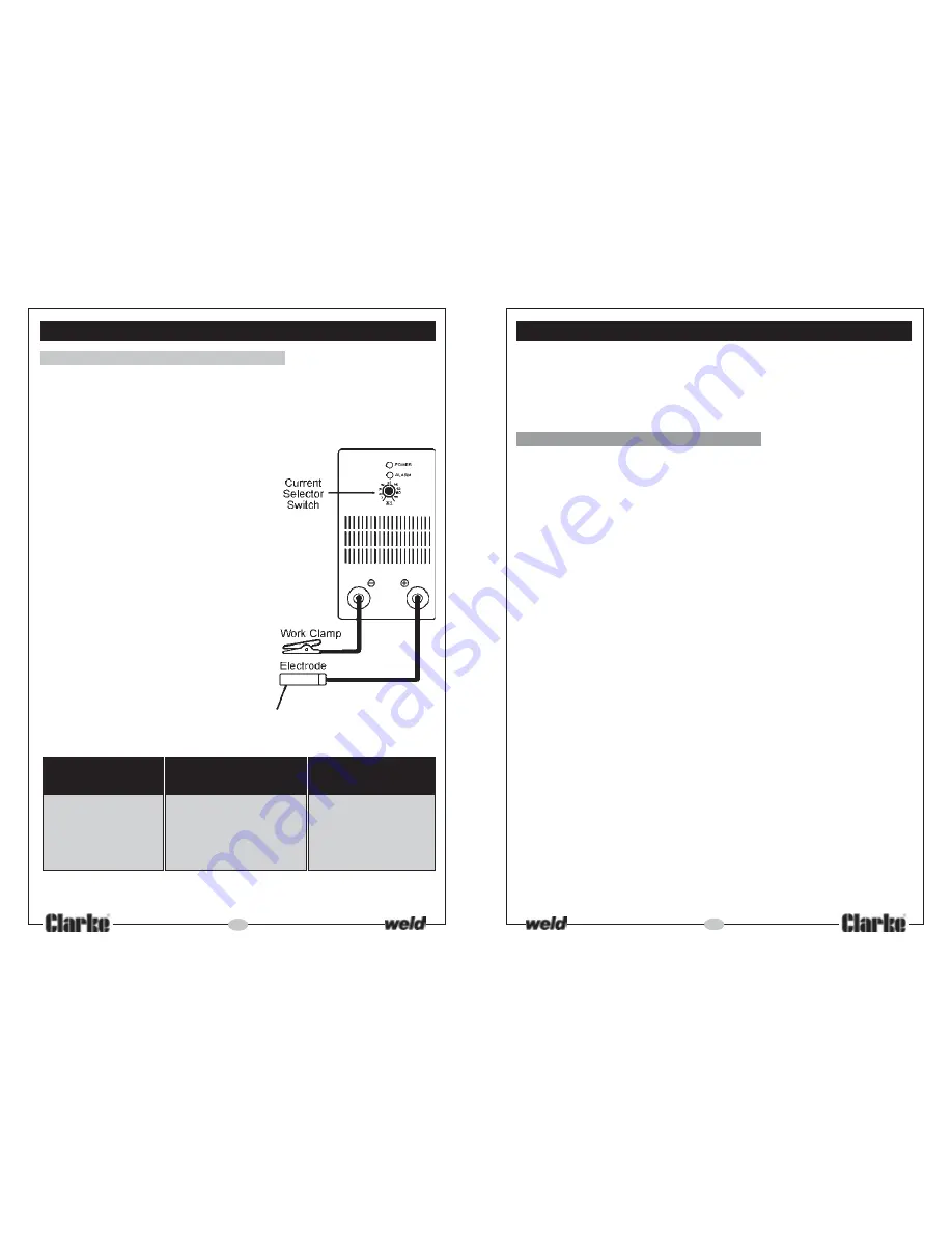
A. ARC WELDING
(Refer to Fig 1.)
Arc welding cables are not supplied with this machine. We recommend the use of
CLARKE ARC WELDING KIT,
which is available from your CLARKE dealer, and is designed
specifically for this machine.
The kit comprises all necessary cables, plus a hand shield and wire brush with chipping
pick.
To prepare the unit for ARC welding, it is
important that you follow the procedure
below.
1.
With the ON/OFF switch, located on the rear
panel, in the OFF position, connect the
welding leads as follows:
Welding Electrode lead to the +ve terminal
Work Clamp lead to the -ve terminal.
2.
Attach the work clamp to the workpiece
- as close as possible to the area being
welded. Clean with a wire brush where
necessary to ensure the connection is as
clean as possible.
3.
An appropriate current must then be set by
turning the Welding Current Selector located
on the front panel of the machine. With
practice you will gain a feel for the correct
current setting for different welding rod
thicknesses.
The size (diameter) of welding rod should
be approximately the same as the thickness of metal to be welded.
For beginners, the following table gives some useful guidelines.
SIZE OF
THICKNESS
CURRENT
WELDING ROD
OF WORKPIECE
SETTING (AMPS)
1.5mm
16 SWG - 1.5 MM.
30 - 40
2.0mm
14 SWG - 2.0 MM.
50 - 65
2.5mm
12 SWG - 2.5 MM.
70 - 100
3.0mm
10 SWG - 3.25MM
100 - 130
4.
Switch ON using the switch located on the rear panel. The green light on the
front panel should glow, indicating the machine is ON.
WELDING TECHNIQUES
Fig 1


