background image


Live View  

ClareVision Plus Network Video Recorder User Manual  

43 

Setting cameras order 

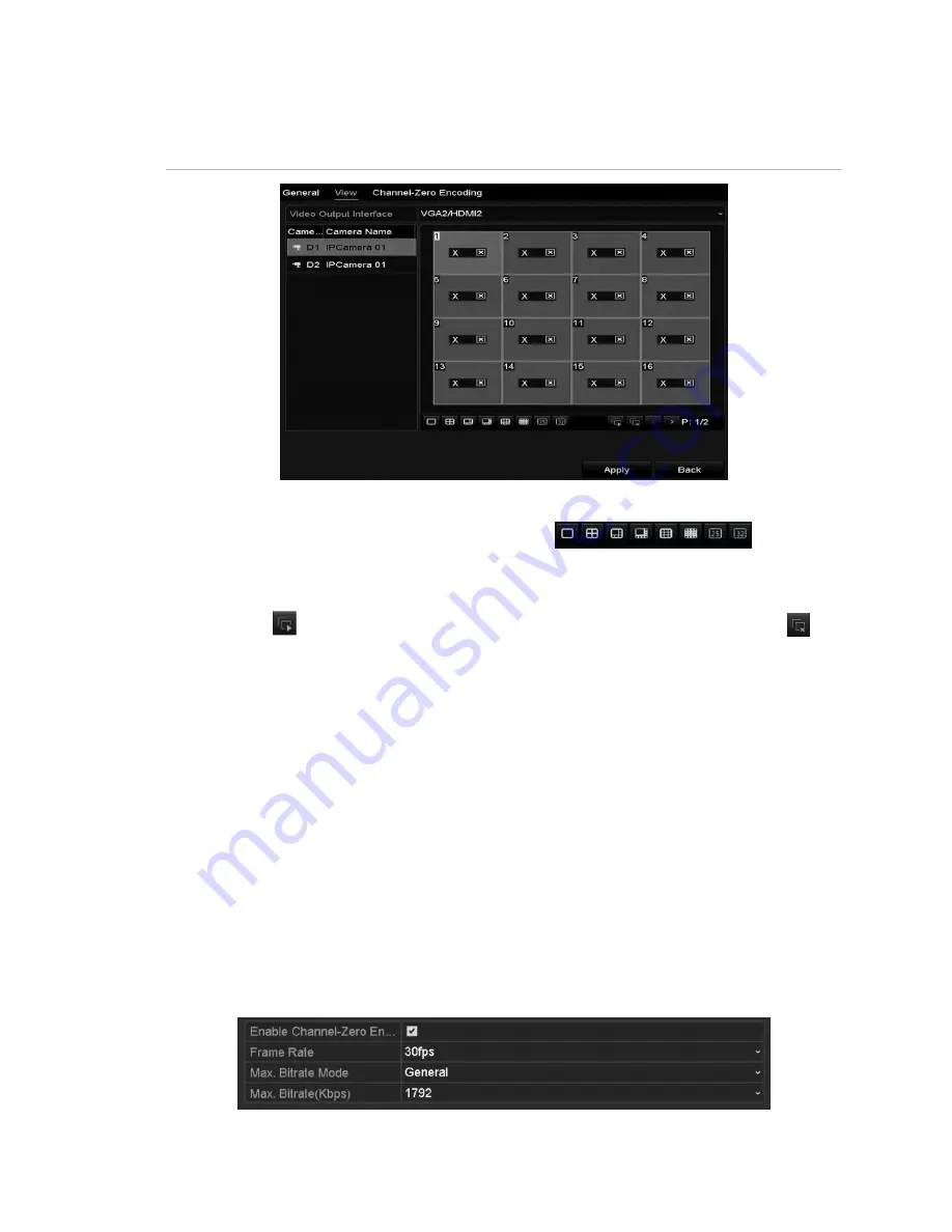
Figure 22: Live View 

– camera order 


To set the camera order: 

1.  Select a view


mode using the toolbar icons


2.  Select the small window, and then double-click the channel number to display 

the channel in the window. 

3.  Click the 

 button to start live view for all the channels, and then click 

 to 

stop all live viewing. 

4.  Click the 

Apply

 button to save the setting. 

Channel-zero encoding 

Sometimes a remote view of channels in real time from a web browser or CMS 
(Client Management System) software is necessary. In order to decrease the 
bandwidth requirement without affecting image quality, channel-zero encoding is 
supported. 

To configure channel-zero encoding: 

1.  Enter the Live View Settings interface. 

Menu

 > 

Configuration

 > 

Live View


2.  Select the 

Channel-Zero Encoding 

tab. 


Summary of Contents for ClareVision Plus

Page 1: ...ClareVision Plus Network Video Recorder User Guide Last Modified 06 08 17 DOC ID 1431 Rev 02 ...

Page 2: ...on Plus Network Video Recorder User Manual name and logo are trademarks of Clare Controls LLC Other trade names used in this document may be trademarks or registered trademarks of the manufacturers or vendors of the respective products Manufacturer Clare Controls LLC 7519 Pennsylvania Ave Suite 104 Sarasota FL 34243 USA Contact information Clare Controls LLC 7519 Pennsylvania Ave Suite 104 Sarasot...

Page 3: ......

Page 4: ...and out 24 Adding and connecting the IP cameras 25 Activating the IP cameras 25 Adding the online IP cameras 26 Editing the connected IP cameras and configuring customized protocols 29 Configuring the customized protocols 31 Editing IP cameras connected to the PoE interfaces 32 Live View 35 Live View icons 35 Operations in Live View mode 35 Front panel operation in Live View 36 Using the mouse in ...

Page 5: ...ure 69 File protection 70 Playback interface 72 Play recorded files 73 Playing back by channel 73 Playing back by event search 74 Playing back by tag 75 Playing back with Smart Playback 77 Playing back by system logs 79 Playing back external file 81 Playing back by sub periods 81 Playing back pictures 82 Auxiliary functions of playback 83 Playing back frame by frame 83 Digital zoom 84 Managing fil...

Page 6: ...detection 115 Audio exception detection 116 Sudden scene change detection 117 Defocus detection 117 PIR alarm 117 Face search 118 Behavior search 120 Plate search 121 People counting 122 Heat map 122 Configuring general settings 124 Configuring advanced settings 125 Configuring PPPoE settings 125 Configuring Cloud P2P 125 Configuring DDNS 126 ClareVision DDNS 127 IPServer 127 PeanutHull 127 NO IP ...

Page 7: ...rmware 151 Initializing HDDs 152 Managing Network HDD 153 Managing eSATA 155 Managing the HDD group 156 Setting HDD groups 156 Setting the HDD property 157 Configuring Quota mode 158 Configuring disk clone 159 Checking HDD status 161 HDD detection 162 Configuring HDD error alarms 163 Configuring OSD settings 164 Configuring privacy mask 165 Configuring video parameters 166 Viewing system informati...

Page 8: ...ClareVision Plus Network Video Recorder User Manual v Configuring DST settings 176 Configuring more settings 177 Managing user accounts 178 Adding a user 178 Deleting a user 181 Editing a user 182 ...

Page 9: ...possibility of such damages and regardless of whether any remedy fails of its essential purpose Installation in accordance with this manual applicable codes and the instructions of the authority having jurisdiction is mandatory While every precaution has been taken during the preparation of this manual to ensure the accuracy of its contents Clare Controls LLC assumes no responsibility for errors o...

Page 10: ...ClareVision Plus Network Video Recorder User Manual vii ...

Page 11: ......

Page 12: ... use TX RX Blinks blue when the network connection is functioning properly GUARD Guard indicator turns blue when the device is in armed status The indicator turns off when the device is unarmed Pressing and holding the ESC button for more than three seconds in Live View mode can change the arm disarm status 2 IR Receiver Receiver for the IR remote 3 Front Panel Lock Lock or unlock the panel with t...

Page 13: ...k box fields pressing the button will check the box In PTZ Control mode the button adjusts the iris of the camera Use in Playback mode to generate video clips for backup Enter or exit the folder of USB device and eSATA HDD MAIN SPOT ZOOM Switch between main and spot output Use in PTZ Control mode to zoom out of the image F1 LIGHT Select all items on the list when used in a list field In PTZ Contro...

Page 14: ...ement of the PTZ camera ENTER The ENTER button is used to confirm selection in any of the menu modes Use to check the check box fields In Playback mode it is used to play or pause the video In single frame Playback mode pressing the button will advance the video by a single frame In Auto switch mode use to stop start auto switch 9 JOG SHUTTLE controls Move the active selection in a menu It will mo...

Page 15: ... enter is used to play pause the video In a single frame play mode pressing Enter plays the video by single frames In auto sequence vide mode the buttons are used to pause resume auto sequence 3 Direction In menu mode the direction buttons navigate between different fields and items In playback mode the up down buttons speed slow the record playing The left right buttons skip forward backward 30s ...

Page 16: ...R top panel Model CVP B4450 01 Table 3 4 Channel CVP B4450 01 mini NVR panel buttons No Name Description 1 Power The POWER LED turns red when NVR is powered up 2 HDD The HDD LED turns red when data is being read or written HDD 3 Network Connection The Network Connect LED flashes blue when functioning ...

Page 17: ...op panel Model CVP B8850 02 Table 4 4 Channel CVP B4450 01 mini NVR panel buttons No Name Description 1 Power The POWER LED turns red when NVR is powered up 2 HDD The HDD LED turns red when data is being read or written HDD 3 Network Connection The Network Connect LED flashes blue when functioning ...

Page 18: ...t Display local video output and menu 6 USB interface Connects USB devices for example a USB mouse or writer 7 RS 232 interface Connector for RS 232 devices 8 eSATA optional Connects external SATA HDD CD DVD RM 2 eSATA interfaces 9 Controller Port D Plus D pin connects to Ta Tb pin of controller For cascading devices the first NVR s D Plus D pin connects with the D Plus D pin of the next NVR ALARM...

Page 19: ...output 3 LINE IN RCA connector for audio input 4 HDMI HDMI output connector 5 USB interface Connects USB devices for example a USB mouse or writer 6 RS 232 interface Connector for the RS 232 devices 7 VGA DB9 connector for VGA output 8 RS 485 interface Half duplex connector for RS 485 devices 9 ALARM IN Connector for alarm input ALARM OUT Connector for alarm output 10 GROUND Ground must be connect...

Page 20: ...connection 2 AUDIO IN RCA connector for audio input Also for two way audio 3 HDMI HDMI video output connector 4 Network interface Connector for LAN 5 AUDIO OUT RCA connector for audio output 6 VGA DB9 connector for VGA output Display local video output and menu 7 USB Connects USB devices for example a USB mouse or writer 8 Ground Ground needs to be connected before the NVR starts up 9 Network Inte...

Page 21: ...connection 2 AUDIO IN RCA connector for audio input Also for two way audio 3 HDMI HDMI video output connector 4 Network interface Connector for LAN 5 AUDIO OUT RCA connector for audio output 6 VGA DB9 connector for VGA output Display local video output and menu 7 USB Connects USB devices for example a USB mouse or writer 8 Ground Ground needs to be connected before the NVR starts up 9 Network Inte...

Page 22: ...hanumeric buttons on front panel 4 EDIT button Same as EDIT IRIS Plus button on front panel 5 A button Same as A FOCUS Plus button on front panel 6 REC button Same as REC SHOT button on front panel 7 PLAY button Same as the PLAY AUTO button on front panel 8 INFO button Reserved 9 VOIP MON button Same as the MAIN SPOT ZOOM button on front panel 10 MENU button Same as the MENU WIPER button on front ...

Page 23: ...t the remote control 1 Go to Menu Settings General More Settings using the front control panel or the mouse 2 Check and remember the NVR ID The default ID number is 255 This ID number is valid for all the IR remote controls 3 Press the DEV button on the remote control 4 Enter the NVR ID number from step 2 5 Press ENTER on the remote If the Status indicator on the front panel turns blue the remote ...

Page 24: ...ovider Table 10 Mouse control Name Action Description Left click Single click Live view Select channel and show the quick set menu Menu Select and enter Double click Live view Switch between single screen and multi screen Click and drag PTZ control Pan tilt and zoom Video tampering privacy mask and motion detection Select target area Digital zoom in Drag and select target area Live view Drag chann...

Page 25: ...ption Use the soft keyboard to enter text Click to view the numeric keyboard Figure 10 Soft alpha numeric keyboard Figure 11 Soft numeric keyboard Table 11 Soft keyboard icons Icon Description Exit Space Alpha numeric keyboard Symbols Backspace Numeric keypad Lowercase uppercase Reserved ...

Page 26: ... indicator LED on the front panel is red indicating the device is getting power 2 Press the power button on the front panel The power indicator LED turns blue indicating start up 3 After startup the Power indicator LED will remain blue A splash screen with the status of the HDD appears on the monitor Click the Live View screen to view the Quick menu The Quick menu a row of icons at the bottom of t...

Page 27: ...Getting Started 16 ClareVision Plus Network Video Recorder User Manual Figure 12 Right click menu Figure 13 Top menu ...

Page 28: ...menu To shut down the NVR from the front panel Option 2 1 Press and hold the power button on the front panel for three seconds 2 Enter the administrator s username and password in the dialog box for authentication 3 Click Yes Note Do not press the power button again when the system is shutting down Rebooting the NVR Reboot the NVR in the Shutdown menu To reboot the NVR from the Shutdown menu 1 Cli...

Page 29: ...ou must set activate it by setting an admin password The NVR cannot be used until it has been activated To activate the NVR 1 The Activation dialog displays enter and confirm a password 2 Click OK Note When updating the NVR to a newer version the following dialog displays Click YES and then follow the wizard to set a password ...

Page 30: ...s as shown in Figure 15 Figure 15 Wizard interface To use the Wizard 1 The Wizard walks you through important settings of the NVR If you do not want to use the Wizard click the Cancel button You can choose to use the Wizard the next time you use the NVR by selecting the Start wizard when the device starts check box 2 Click Next to enter date and time window ...

Page 31: ...gs click Next You are returned to the Network Setup Wizard window Note Dual NIC is only available in the 64 Channel NVR device For all other NVRs configure the internal NIC IPv4 address for the cameras connecting to the PoE network interface of the NVR 4 Click Next and then configure the Cloud P2P settings ...

Page 32: ...ClareVision Plus Network Video Recorder User Manual 21 5 Click Next and then configure the advanced network parameters as desired 6 Click Next the RAID interface displays Note RAID is only available on 64 channel NVRs ...

Page 33: ... click Next The Array Management interface displays 8 Enter the Array name and then click Next The HDD Management interface displays 9 Click Init to initialize the HDD Note Initialization removes all data saved in the HDD 10 Click Next to enter the Adding IP Camera interface 11 Click Search to search for the online IP camera ...

Page 34: ...ve Before adding a camera it must be in the active state If the camera is inactive click the inactive camera icon and set the password If there is more than one inactive camera click One touch Activate and all inactive cameras are activated 12 Click Add to add a camera 13 Click Next select the recording settings for the camera and then click OK ...

Page 35: ...e device before you can access the menu or other features To log into the NVR 1 Select the desired user name 2 Enter the password 3 Click OK Note If you enter incorrect log in information 7 times the selected user account is locked for 60 seconds To log out of the NVR 1 Enter the Shutdown menu Menu Shutdown 2 Click Logout 3 Click OK ...

Page 36: ... the IP cameras Activating the IP cameras Before adding an IP camera verify that the camera status is active To activate an IP camera 1 Right click to view the menu and then select Add IP Camera 2 Click the desired camera s inactive icon or click One touch Activate to activate multiple cameras ...

Page 37: ...k camera to the connection list to get a live view and record of the video Before you start ensure that the network connection is correct For detailed instructions about checking and configuring the network see Configuring Virtual Host Checking network traffic and Configuring network detection on page 138 Directly access the IP camera management interface after enabling virtual host To configure v...

Page 38: ...5 Click the link and IP Camera Management IP page displays To add an online camera 1 Right click the mouse in Live View mode to show the dialog window 2 Click to enter the IP camera interface 3 Select the detected IP camera and then click Add or Custom add an IP camera by editing the parameters in the corresponding text field and then clicking Add Note Click Search to refresh the online IP cameras...

Page 39: ... the Camera Management interface 1 Browse to Camera Menu Camera Camera 2 Cameras with the same network are detected 3 Select the camera and then click or Click One touch Adding to add all cameras 4 For encoders with multiple channels Select the Channel Port and then click OK to add the channels ...

Page 40: ...rotocols After adding the IP cameras the basic settings are listed on the page Configure the basic settings of each IP camera To configure the basic settings 1 Click to edit the parameters 2 Click OK to save the settings and exit the window To edit advanced parameters 1 Drag the horizontal scroll bar to the right side and then click ...

Page 41: ...Getting Started 30 ClareVision Plus Network Video Recorder User Manual 2 Edit the network information and password for the camera 3 Click Apply to save the settings and then click OK to exit the window ...

Page 42: ...col type and then select the transfer protocols Before customizing the camera s protocol you must contact the camera s manufacturer to consult the URL uniform resource locator for the main and sub streams URL format Type IP Address of the network camera Port Path Example rtsp 192 168 1 55 554 ch1 main av_stream Protocol Name Edit the name for the custom protocol Enable Substream If the network cam...

Page 43: ...ocol you added to validate connection to the network camera Editing IP cameras connected to the PoE interfaces Note Not all ClareVision Plus NVRs have PoE make sure that your NVR supports PoE The PoE interface allows the NVR system to pass electrical power and data through Ethernet cables Up to eight PoE interfaces can connect to the network cameras To use an online network camera you must first d...

Page 44: ...ameras connecting to the PoE interface in this menu 2 Click and then select the Adding Method 3 Choose one of the following adding methods Plug and Play Connect the camera to the PoE interface You cannot edit the camera parameters when choosing this option The camera s IP address can only be edited in the Network Configuration interface See Configuring general settings on page 124 for detailed inf...

Page 45: ...on Plus Network Video Recorder User Manual Manual This disables the PoE interface The current channel is then used as a regular channel with configurable parameters Enter the IP address the user name and password and then click OK ...

Page 46: ...set See Setting alarm response actions on page 104 Note This icon appears in the lower left corner Operations in Live View mode The Live View mode functions are listed below Single Screen Shows only one screen on the monitor Multi screen Shows multiple screens on the monitor simultaneously Auto switch The screen is auto switched to the next one You must set the dwell time for each screen on the co...

Page 47: ...ction is invalid HDMI VGA and CVBS is used at the same time When the Aux output is enabled the main output cannot operate Some basic operations are performed in the Live View mode for the Aux output Front panel operation in Live View Table 14 Front panel operation in Live View mode Functions Front Panel Operation Common menu Provides quick access to the sub menus most often visited Up to 5 sub men...

Page 48: ...tart playing back the video of the selected channel immediately PTZ Enters the PTZ interface Output Mode Four modes of output supported including Standard Bright Gentle and Vivid Aux Monitor Switches to the auxiliary output mode and the operation for the main output is disabled Notes If you enter the Aux monitor mode and the Aux monitor is not connected the mouse operation is disabled You must swi...

Page 49: ...selected from a drop down list Multi screen Switch between different display layout options Layout options available in the drop down list Next Screen When displaying less than the maximum number of cameras in Live View clicking this feature switches to the next display set Playback Enters Playback mode PTZ Enters the PTZ Control mode Main Monitor Enters the Main operation mode Note In the Live Vi...

Page 50: ...the recording in last five minutes 2 Digital Zoom can zoom to make the selected area full screen Click and draw to select the area to zoom as shown in Figure 18 3 Click the Image Settings icon to enter the Image Settings menu as shown in Figure 19 You can change the image parameters 4 Live View Strategy is selected to set strategy including Real time Balanced and Fluency as shown in Figure 20 5 Fa...

Page 51: ...Live View 40 ClareVision Plus Network Video Recorder User Manual Figure 18 Digital zoom Figure 19 Image settings preset Figure 20 Live View Strategy ...

Page 52: ...Live View ClareVision Plus Network Video Recorder User Manual 41 Figure 21 Information ...

Page 53: ...ration Live View Table 17 Live View settings Video Output Interface Designates the output for setting configuration Outputs include HDMI depends on the model VGA Main CVBS and Spot Output Live View Mode Designates the display mode used for Live View Dwell Time The time in seconds to dwell between switching channels when auto switch is enabled in Live View Enable Audio Output Enables disables audio...

Page 54: ...rt live view for all the channels and then click to stop all live viewing 4 Click the Apply button to save the setting Channel zero encoding Sometimes a remote view of channels in real time from a web browser or CMS Client Management System software is necessary In order to decrease the bandwidth requirement without affecting image quality channel zero encoding is supported To configure channel ze...

Page 55: ...Check the check box after Enable Channel Zero Encoding 4 Configure the Frame Rate Max Bitrate Mode and Max Bitrate 5 Click the Apply to save the settings After you set the Channel Zero encoding you can view 16 channels in one screen using a remote client or web browser ...

Page 56: ... Configuring PTZ settings Follow the procedure to set the parameters for PTZ Pan Tilt Zoom You should configure the PTZ parameters before you control the PTZ camera To configure PTZ settings 1 Enter the PTZ Settings interface Menu Camera PTZ 2 Click PTZ Parameters ...

Page 57: ... the settings Setting PTZ presets patrols and patterns Note Make sure that the presets patrols and patterns are supported by PTZ protocols Customizing presets Follow the steps below to set the preset location for the PTZ camera to point when an event takes place To set the preset location 1 Browse to the PTZ Control interface Menu Camera PTZ 2 Use the direction buttons to move the camera to the de...

Page 58: ...eature allows the camera to point to a specified position such as a window when an event takes place To call preset in the PTZ setting interface 1 Browse to the PTZ Control interface Menu Camera PTZ 2 Click the PTZ Control icon in the quick setting bar or Select the PTZ option in the right click menu 3 Select the desired camera from the Camera drop down list 4 Click to view the general PTZ control...

Page 59: ...Patrols can be set to move the PTZ to different key points dwell for a set time and move to the next key point To customize patrols 1 Browse to the PTZ Control interface Menu Camera PTZ 2 Select the patrol number from the patrol drop down 3 Click Set to add key points presets to the patrol ...

Page 60: ...y point The Speed defines the speed at which the PTZ moves from one key point to the next 5 Click Add to add another key point to the patrol or Click OK to save the key point patrol Calling patrols Calling a patrol makes the PTZ camera move according to the predefined patrol path To set calling patrol in the PTZ setting interface 1 Click the PTZ Control icon in the quick setting bar or Select the ...

Page 61: ...nu Camera PTZ 2 Select the pattern number in the Pattern drop down 3 Click Start and then click the corresponding control panel buttons to move the PTZ camera 4 When finished click Stop The movement of the PTZ is recorded as the pattern Calling patterns Follow the procedure to move the PTZ camera according to the predefined patterns To set a calling pattern in the PTZ setting interface 1 Click the...

Page 62: ...eneral PTZ control settings 3 Click Call Pattern 4 When finished click Stop Pattern Customizing the linear scan limit The linear scan limit is enabled to trigger a horizontal scan in a predefined range To customize the linear scan limit 1 Browse to the PTZ Control interface Menu Camera PTZ ...

Page 63: ...ed 180 Calling linear scan Before using this feature verify that the camera supports linear scan and is using ClareVision Plus protocol To call the linear scan 1 Click the PTZ Control icon in the quick setting bar or Select the PTZ option in the right click menu 2 Click to view the general PTZ control settings 3 Click Linear Scan to start the scan and then click Linear Scan to stop the scan or Cli...

Page 64: ...fter the park time An undefined preset is skipped Park Patrol 1 After the park time the dome starts moving according to the predefined patrol path Park Preset 1 After the park time the dome moves to the predefined preset 1 location 4 Click the button again to deactivate the one touch settings PTZ control panel Access the PTZ control panel using an option below Option 1 In the PTZ settings interfac...

Page 65: ... mouse connection the PTZ icon appears in the lower left corner indicating that the camera is in PTZ control mode Figure 23 PZT panel Table 18 PZT panel icons Direction and auto cycle buttons Zoom Plus Focus Plus Iris Plus Zoom Focus Iris PTZ movement speed Light on off Wiper on off 3D zoom Image centralization Menu Previous item Next item Start pattern patrol Stop the patrol pattern movement Mini...

Page 66: ...on Note The HDD must be installed and initialized before configuring the parameters To prepare the HDD 1 Make sure that the HDD is installed If not install and initialize it now Menu HDD General 2 Check the storage mode of the HDD a Click Advanced to check the storage mode of the HDD b If the HDD mode is set to Quota set the maximum record capacity and maximum picture capacity c If the HDD mode is...

Page 67: ...r example when an alarm triggers the recording ends at 11 00 and you set the post record time as 5 seconds it records till 11 00 05 Expired Time The expired time days is the longest time for the NVR to keep a recorded file in the HDD When it reaches its deadline the NVR deletes the file You can set the expired time to 0 to prevent the file from being deleted The HDD capacity determines the actual ...

Page 68: ...nishment function via the web browser Configuration Camera Settings Schedule Settings Advanced to save the recording files in the IP camera when the network is disconnected and then have the files synchronize in the NVR when the network is resumed 4 Enter the Sub stream tab page 5 Configure the parameters of the camera 6 Click Apply to save the settings 7 Select the Capture tab and then configure ...

Page 69: ...he Capture tab in the Schedule interface To configure the schedule 1 Enter the Record Schedule interface Menu Record Capture Schedule 2 Select Record or Capture Schedule There are 6 differed recording types Continuous Scheduled recording Event Event triggered recording Motion Motion detection triggered recording Alarm Alarm triggered recording M A Motion detection or alarm triggered recording M A ...

Page 70: ... choose the day when you want to set a schedule 2 Click to set the schedule time 3 To schedule an all day recording select the All Day checkbox 4 To arrange another schedule set the start and end time Do not select the All Day checkbox You can configure up to eight schedules for each day The schedules cannot overlap each other ...

Page 71: ...gs or captures for other days in the week To apply the schedule to other days click Copy 6 Click OK to save the setting and return to the previous menu 7 Click Apply to save the settings in the Record menu To draw the schedule 1 Click the color icons Set the schedule type as continuous or event 2 Click Apply to save the settings ...

Page 72: ...ameters In the Live View mode once a motion detection event takes place the NVR can analyze it and respond Enabling the motion detection function can trigger certain channels to start recording trigger full screen monitoring audio warning notify the surveillance center and so on In this chapter you can follow the steps to schedule a recording triggered by detected motion To configure motion detect...

Page 73: ...rea To select the camera s entire field of view click Full Screen To clear the motion detection area click Clear 4 Click Settings 5 Select the channels you want the motion detection events to trigger recording 6 Click Apply to save the settings 7 Click OK to return to the previous menu 8 Exit the Motion Detection menu and then edit the Motion Detection Record Schedule See Configuring record captur...

Page 74: ...gered record and capture To configure alarm triggered recording or capture 1 Browse to the Alarm setting interface Menu Configuration Alarm 2 Click Alarm Input 3 Select Alarm Input No and then configure alarm parameters Set the Alarm Type N O normally open or N C normally closed Select the Enable checkbox ...

Page 75: ...he desired channel checkbox 7 Click Apply to save settings and then click OK to return to the previous menu 8 Repeat the above steps to configure other alarm input parameters If you want to apply the settings to other alarm inputs click Copy and choose the alarm input number 9 Edit the Alarm triggered record in the Record Capture Schedule setting interface ...

Page 76: ... Manual or Press the REC SHOT button on the front panel 2 To enable manual record select Record on the left bar 3 Click the status button before the desired camera number to change from OFF to ON To disable manual record 1 Click the status button to change ON to OFF Note The green ON icon indicates that the channel is configured in the record schedule After rebooting all the manual records that we...

Page 77: ... that the channel is configured to a capture schedule After rebooting all continuous captures are canceled Configuring holiday record and capture Follow the steps below to configure the record or capture schedule for holidays You may have different plans for recording and capture on holidays To configure holiday record and capture 1 Browse to the Record setting interface Menu Record Holiday ...

Page 78: ...the start and end date 6 Click Apply to save your settings 7 Click OK to exit the Edit interface 8 Enter the Record Capture Schedule interface and edit the holiday recording schedule Configuring redundant recording and capture Enable redundant recording and capture to save the record files and captured pictures in the R W HDD and in the redundant HDD if available This will enhance the data safety ...

Page 79: ...u Note Prior to setting the HDD property to Redundant set the Storage mode to Group There should be another HDD in Read Write status 6 Browse to the Record setting interface Menu Record Parameters 7 Click the Record tab and then click More Settings 8 Select the desired camera from the drop down list and then select the Redundant Record Capture checkbox 9 Click OK to save settings and return to the...

Page 80: ... 5 Click to enter editing interface 6 Choose a group number for the HDD group 7 Click Apply and then click Yes to save your settings 8 Click OK to return to the previous menu Repeat the above steps to configure more HDD groups To choose the channels that you want to save 1 Click Advanced on the left bar 2 Select the group number in the Record on HDD Group drop down list 3 Check each desired channe...

Page 81: ... files 1 Browse to the Export setting interface Menu Export 2 Select the desired channels and then double click on the calendar to select the date 3 During playback click to lock the current file Note In multi channel playback mode clicking locks all recorded files related to the selected playback channels 4 Click to access the file management interface 5 Click the Locked File tab to check and exp...

Page 82: ... must set the storage mode of the HDD to Group See Managing the HDD group on page 156 3 Set the HDD property to Read only 4 Click OK to save the settings and return to the previous menu Notes You cannot save files in a read only HDD If you want to save files in the HDD change the property to R W If there is only one HDD and it is set to read only the NVR cannot record any files Only live view mode...

Page 83: ...trol play progress as shown in the figure below Click the channel s to execute simultaneous playback of multiple channels Note The indicates the start end time of the record Table 19 Playback icons Icons Description Audio on Mute Start Stop clipping 30s forward 30s backwards Capture frame Lock video Add default tag Add customized tag ...

Page 84: ...ar use the mouse to click any point of the progress bar or drag the progress bar to locate special frames Play recorded files Playing back by channel Play back the recorded video files of a specific channel in the Live View mode You have two playback options for play back To use instant playback 1 Click in the quick setting toolbar to choose a channel in Live View mode Note In instant playback mod...

Page 85: ...rface Click in the right click menu Playing back by event search Play back record files on one or several channels searched out by restricting event type e g alarm input and motion detection To play back by event search 1 Browse to the Playback interface Menu Playback 2 Select Event in the top left drop down list ...

Page 86: ...art time and End time 6 Click Search for result information Refer to the right side bar for the result 7 Click to play the file Note You can configure pre and post play 8 Use the toolbar at the bottom of the Playback interface to control playback Playing back by tag Video tags let you mark specific points in recording Use tags to search for people locations or set custom tags Use video tags to sea...

Page 87: ...erface Menu Playback 2 Search and play back the record files 3 Click to add default tag 4 Click to add customized tag and input tag name Note There is a maximum of 64 tags in a single video file To manage tags 1 Click to check edit and delete tags 2 Select the tag from the drop down list in the Playback interface ...

Page 88: ...ntaining the motion VCA information makes it in green and plays it at normal speed while the video without motion is played at the 16 time speed Configure the Smart Playback rules and areas Note Before using Smart Playback the corresponding even type must be enabled and configured in the IP camera For example to use Smart Playback with Intrusion Detection Intrusion Detection must be enabled in the...

Page 89: ... in the line Intrusion Detection Click and hen specify the 4 points creating a quadrilateral region for intrusion detection Only 1 region can be configured Motion Detection Click and then click drag the mouse setting the detection area manually Click to select the full screen 6 Click to configure smart settings Skip the Non Related Video Non related video is not played when this function is enable...

Page 90: ...iles by setting target characters including gender age and whether they have glasses Playing back by system logs Play back record files associated with channels after searching the system logs To play back by system logs 1 Browse to the Log Information interface Menu Maintenance Log Information 2 Click the Log Search tab to enter Playback by System Logs ...

Page 91: ...type and then click Search 4 Select a log with record files and click to enter the Playback interface Note If there is no record file at the time point of the log the No result found dialog box displays 5 Use the toolbar in the bottom part of the Playback interface to control playing process ...

Page 92: ...ft drop down select External File The files are listed to the right side of the screen Click Refresh to refresh the file list 3 Select a file and then click to play the file Playing back by sub periods Play the video files back in multiple sub periods simultaneously on screen To play back sub periods 1 Browse to the Playback interface Menu Playback 2 In the upper left corner drop down select Sub p...

Page 93: ... if the video file is between 4am and 8am and the 4 screen display mode is selected then 1 hour video files are displayed simultaneously Playing back pictures Search for and view pictures captured and stored in a device s HDD To play back pictures 1 Browse to the Playback interface Menu Playback 2 In the top left drop down select picture 3 Select the channel channels and specify the search start a...

Page 94: ...layback interface to control and navigate through the images Table 20 Picture playback toolbar Icons Description Revers Play Previous picture Next picture Auxiliary functions of playback Playing back frame by frame Play video files frame by frame to check the image details of the video when abnormal events occur To play back frame by frame using a mouse 1 Browse to the Playback interface Menu Play...

Page 95: ...oolbar To play back frame by frame using the front panel 1 Hold and rotate the outer ring on the Jog Shuttle counter clockwise for 16 and 32 Channel only or click to set the speed to Single frame One click on Pause button single click on the playback screen or Enter button on the front panel represents playback or reverse playback of one frame Digital zoom To use digital zoom 1 Click to enter the ...

Page 96: ...All to export all files to a local storage device or Click Export to export a specific file Reverse playback of multi channel Simultaneous playback is supported for multi channel Up to 16 channel with 1280 720 resolution simultaneous reverse playback is supported up to 4 channel with 1920 1080 resolution simultaneous reverse playback is supported and up to 1 channel with 2560 1920 resolution rever...

Page 97: ...back 86 ClareVision Plus Network Video Recorder User Manual 2 Select more than one check box to select multiple channels and then click to select a date on the calendar 3 Click to play the files in reverse ...

Page 98: ...iles Quick export Export recorded files to backup devices quickly To use quick export 1 Browse to the Export interface Menu Export Normal 2 Select the desired channels and then click Quick Export 3 Select the format that the logs are exported to Select up to 9 formats ...

Page 99: ...ion Plus Network Video Recorder User Manual 4 Click Export Note Do not leave this menu until all files are successfully exported there is a finished dialog 5 Choose the record file in the Export interface and then click ...

Page 100: ...riter SATA writer and e SATA HDD Note The CVP P64050 10 is the only ClareVision Plus model that supports eSATA HDD To backup using USB flash drives and USB HDDs Note The following instructions are the same for USB writer and SATA writer Follow the steps below 1 Browse to the Export interface Menu Export Normal Picture 2 Select the cameras 3 Set the search conditions and then click Search ...

Page 101: ...ed chart list Note The size of the selected files displays in the lower left corner of the window 5 Click Export Export All and start backup Note If the inserted USB device is not recognized do the following Click the Refresh button Reconnect device Check the vendor s compatibility You can format USB flash drives or USB HDDs via the device ...

Page 102: ... Back up event related record files using USB devices USB flash drives USB HDDs USB writer SATA writer or eSATA HDD Quick Backup and Normal Backup are supported To back up by event search 1 Browse to the Export interface Menu Export Event 2 Select the cameras 3 Set the event type to alarm input motion or VCA 4 Configure the search conditions and then click Search The matching video files are displ...

Page 103: ... clips to export directly during Playback using USB devices USB flash drives USB HDDs USB writer SATA writer or eSATA HDD To backup video clips 1 Browse to the Playback interface Menu Export Event 2 During playback click and to start or stop clipping record files or click to capture pictures 3 Click to access the file management interface 4 Export the video clips pictures ...

Page 104: ...he backup device Note If the inserted device is not recognized do the following Click the Refresh button Reconnect device Check the vendor s compatibility Hot Spare device back up The device can form an N Plus1 hot spare system The system consists of several working devices and a hot spare device When the hot spare device switches into operation it increases the reliability of the system Note Plea...

Page 105: ...e after each mode switch To configure the hot spare device 1 Browse to the Hot Spare settings interface Menu Configuration Hot Spare 2 Set the Word Mode to Hot Spare Mode and then click Apply 3 Reboot the device for the changes to take effect To set the working device 1 Browse to the Hot Spare settings interface Menu Configuration Hot Spare 2 Set the Word Mode to Normal Mode default 3 Select the E...

Page 106: ...hot spare device 5 Click Apply To manage the hot spare system 1 Browse to the Hot Spare settings interface Menu Configuration Hot Spare 2 Select the desired working device s checkbox and then click Add to link the working device to the hot spare device Note A hot spare device can connect up to 32 working devices ...

Page 107: ...ice goes offline the hot spare device records the video of the IP camera connected to the working device as backup The working status of the hot spare device displays as Backing up Note The record backup functions for 1 working device at a time When the working device comes online the lost video files are restored through the record synchronization function and the working status displays Synchron...

Page 108: ...amera for motion detection Menu Camera Motion 2 Select the Enable Motion Detection checkbox 3 Using the mouse draw a detection area and then drag the sensitivity bar to adjust the sensitivity 4 Click and then set the alarm response actions 5 Click the Trigger Channel tab and then select the desired channels to record and capture or become full screen monitoring when the motion alarm is triggered ...

Page 109: ...e week and up to eight time periods on that day 9 Click Apply to save the settings Note Do not repeat or overlap times 10 Click the Handling tab to set up the alarm response actions for the motion alarm 11 If you want to set motion detection for another channel repeat the steps above or simply click Copy in the Motion Detection interface to copy the settings ...

Page 110: ...ings of System Configuration and select an alarm input Menu Configuration Alarm 2 Click the Alarm Input tab 3 Select the Enable checkbox and then click Settings to set the alarm response actions 4 Click the Trigger Channel tab and then select one or more channels to record and capture or become full screen monitoring when an external alarm is detected 5 Click Apply to save the settings ...

Page 111: ...bove steps to configure the arming schedule for other days or Click Copy to copy an arming schedule to other days 9 Select the Linkage Action tab to set up alarm response actions of alarm input If necessary select the PTZ Linking tab and set PTZ linking parameters and then click OK Note Ensure the PTZ or speed dome supports PTZ linkage One alarm input can trigger the presets patrol or pattern of o...

Page 112: ...twork Video Recorder User Manual 101 10 If you want to set the handling action of another alarm input repeat the above steps You can also click Copy and then select the checkbox for the desired alarm inputs and copy the settings to them ...

Page 113: ... you want to detect Menu Camera Video Loss 2 Select the Enable Video Loss Alarm checkbox and then click to set up the video loss handling actions 3 Click the Arming Schedule tab to set the channel s arming schedule 4 Select a day of a week and up to eight times for that day 5 Click Apply to save the settings Note Do not repeat or overlap times 6 Click the Linkage Action tab to set up alarm respons...

Page 114: ...nnel Menu Camera Video Tampering 2 Check the Enable Video Tampering check box 3 Drag the sensitivity bar to choose a proper sensitivity level 4 Using the mouse draw an area to detect video tampering 5 Click to set the handling action for video tampering 6 Click the Arming Schedule tab to set the arming schedule for handling actions 7 Select a day of a week and up to eight periods for that day 8 Cl...

Page 115: ... ID or password Record Capture Exception No space for saving recorded files or captured images Hot Spare Exception The working device is not connected To set alarm exceptions 1 Browse to the Exception interface of System Configuration and handle various exceptions Menu Configuration Exceptions Setting alarm response actions Alarm response actions activate when an alarm or exception occurs includin...

Page 116: ... BNC monitor displays in full screen If alarms are triggered simultaneously in several channels their full screen images are switched at a ten second interval default dwell time You can set a different dwell time by going to Menu Configuration Live View General Full Screen Monitoring Dwell Time Auto switch terminates once the alarm stops You are then taken back to the Live View interface Note You ...

Page 117: ...mation to a user or users when an alarm is detected Trigger alarm output Trigger an alarm output when an alarm is tripped To configure a trigger alarm 1 Browse to the Alarm Output interface Menu Configuration Alarm Alarm Output 2 Select an alarm output and set alarm name and dwell time 3 Click Schedule to set the arming schedule of alarm output Note When you select Manually Clear on the Dwell Time...

Page 118: ... of the alarm output You can also copy the above settings to another channel Triggering or clearing alarm output manually Sensor alarms are triggered and cleared manually When you select Manually Clear from the Dwell Time list you must clear the alarm by clicking Clear in the Manual Alarm interface Menu Manual Alarm Click Trigger Clear to trigger clear an alarm output Click Trigger All to trigger ...

Page 119: ...lus camera For in depth camera configuration see ClareVIsion Plus Camera User Manual DOC ID 1430 Face recognition To configure a face recognition alarm 1 Browse to the Face Detection interface Menu Camera VCA 2 Select the Enable Face Detection checkbox 3 Click Save Face detection The face detection function detects the appearance of a face in the surveillance scene Configure actions in response to...

Page 120: ...he trigger channel arming schedule and linkage action Refer to Setting motion detection alarms on page 97 5 Click Rule Settings to set the face detection rules and then click and drag the slider to set the desired level of sensitivity Sensitivity The higher the sensitivity value ranges from 1 to 5 the easier a face is detected in the surveillance area 6 Click Apply Vehicle detection The vehicle de...

Page 121: ...ve VCA Picture to save captures pictures from VCA detection 3 Set the VCA detection to Vehicle Detection and then select the Enable checkbox 4 Click to configure the trigger channel arming schedule and linkage actions for the blacklist whitelist the others 5 Click Rule Settings to enter the rule settings interface Configure the lane upload picture and overlay content settings Select up to 4 lanes ...

Page 122: ... detection 3 Set the VCA detection to Line Crossing Detection and then select the Enable checkbox 4 Click to configure the trigger channel arming schedule and linkage actions for the blacklist whitelist the others 5 Click Rule Settings to configure the line crossing detection rules a Select the direction A B A B or A B A B Only the arrow on the B side displays When an object crosses the line going...

Page 123: ... configure intrusion detection 1 Browse to the VCA settings interface Menu Camera VCA 2 Select the desired camera Note Click the Save VCA Picture to save captures pictures from VCA detection 3 Set the VCA detection to Intrusion Detection and then select the Enable checkbox 4 Click to configure the trigger channel arming schedule and linkage actions 5 Click Rule Settings and configure the following...

Page 124: ...triggered Percentage Range 1 to 100 The ratio of the in region part of the object which triggers the alarm For example if the percentage is set at 50 when the object enters the region and occupies half of the entire region the alarm is triggered 6 Click and then draw a quadrilateral by setting the 4 corners Right click to complete drawing the region Notes Only 1 region can be configured Up to 4 ru...

Page 125: ...ve captures pictures from VCA detection 3 Set the VCA detection to Region Entrance Detection and then select the Enable checkbox 4 Click to configure the trigger channel arming schedule and linkage actions 5 Click Rule Settings and configure the following parameters Sensitivity Range 1 to 100 The value of the sensitivity defines the size of the object that triggers the alarm The higher the value t...

Page 126: ...on If the value is set to 10 the alarm is triggered after the vehicle has been in the region for 10s Up to 4 rules can be configured Unattended Baggage detection The unattended baggage detection function detects an object left in a pre defined region Notes The Rule Settings threshold defines the time the object is left in the region If the value is set to 10 an alarm is triggered after 10s The Rul...

Page 127: ...ction function detects abnormal sounds in a surveillance scene For example the sudden increase decrease of a sounds intensity trigger the alarm To configure the audio exception detection 1 Enter the VCA settings interface Menu Camera VCA 2 Select the desired camera 3 Set the VCA detection to Audio Exception Detection and then select the Enable checkbox 4 Click to configure the trigger channel armi...

Page 128: ...e detection function detects the change of the surveillance environment For example when the camera is rotated Note The Rule Settings sensitivity determines how easily the scene change is triggered Defocus detection The image blur caused by a defocused lens is detected Note The Rule Settings sensitivity determines how easily a defocused image triggers an alarm PIR alarm The PIR passive infrared al...

Page 129: ...ace search When there are face detected pictures captured and saved in the HDD enter the Face Search interface to search for the picture and play the related video file according to the specified conditions To configure a face search 1 Browse to the Face Search interface Menu VCA Search Face Search 2 Select the desired cameras 3 Specify the start and end time for the search files ...

Page 130: ...19 4 Click Search The results for face detection are displayed in list or chart form 5 Export the captured face pictures to local storage devices a Connect the storage device b Click Export All to enter the Export interface c Click Export to export all face pictures ...

Page 131: ...or based on VCA detection To configure behavior search 1 Browse to the Behavior Search interface Menu VCA Search Behavior Search 2 Select the desired cameras 3 Specify that start and end time for the search 4 Select the VCA detection type from the drop down 5 Click Search The results for face detection are displayed in list or chart form ...

Page 132: ...arch Search and view for matching vehicle plate pictures and information according to start end time country and plate number To configure plate search 1 Browse to the Plate Search interface Menu VCA Search Plate Search 2 Select the desired cameras 3 Specify that start and end time for the search 4 Select the country and then enter the plate number in the corresponding field 5 Click Search The res...

Page 133: ...sired cameras 3 Select the report type and then set the statistics time 4 Click Counting 5 Click Export to export the statistics report in an Excel file Heat map The heat map is a graphical representation of data presented by colors The map function is used to analyze the visit and dwell times of customers in a configured area Note The heat map function bust be supported by the connected IP camera...

Page 134: ...A Search ClareVision Plus Network Video Recorder User Manual 123 3 Select the report type and then set the statistics time 4 Click Counting 5 Click Export to export the statistics report in an Excel file ...

Page 135: ...he General Settings interface configure the following settings Working Mode NIC Type IPv4 Address IPv4 Gateway MTU and DNS Server Note MTU range is 500 through 9676 4 If the DHCP server is available you can select the DHCP checkbox to automatically obtain an IP address and other network settings from that server Note For the 16 and 32 Channel NVRs you must configure the internal NIC address so tha...

Page 136: ...ce The system prompts you to reboot the device to enable the new settings After the reboot the PPPoE dial up is automatically connected Browse Network Interface Menu Maintenance System Info Network Interface to view the PPPoE connection status Configuring Cloud P2P Cloud P2P provides access for mobile device applications allowing control of the connected NVR Allowing you remote access to the surve...

Page 137: ...u can access and manage the NVR using their mobile phone Configuring DDNS If your NVR is set to use PPPoE as its default network connection set the Dynamic DNS DDNS for network access You must register with your ISP before configuring the system to use DDNS To configure DDNS 1 Enter the Network Settings interface Menu Configuration Network 2 Click the DDNS tab 3 Select the DDNS checkbox to enable ...

Page 138: ...the ClareVision DDNS website 3 Enter the User Name and Password registered in the ClareVision website IPServer Enter the server address for IPServer PeanutHull Enter the User Name and Password obtained from the PeanutHull website NO IP 1 Enter the account information in the corresponding fields 2 Enter the NO IP s server address 3 In the NVR Domain Name field enter the domain obtained from the NO ...

Page 139: ... the following NTP settings Interval Time interval between the two synchronizing actions with NTP server The unit is minute NTP Server IP address of NTP server NTP Port Port of NTP server 5 Click Apply to save and exit the interface Note The time synchronization interval is set from1 to 10080 minutes The default value is 60 minutes If the NVR is connected to a public network you should use an NTP ...

Page 140: ...and configure it to receive the device information via SNMP port By setting the trap address the NVR can send the alarm event and exception message to the surveillance center Configuring the More Settings tab The More Settings tab contains configuration options for the Alarm Host IP Port Multicast IP RTSP Port and Server and HTTP ports Configuring a remote alarm host With a remote alarm host confi...

Page 141: ...recommend that you use IP addresses ranging from 239 252 0 0 to 239 255 255 255 To configure multicast 1 Browse to the Network Settings interface Menu Configuration Network 2 Click the More Settings tab 3 Set multicast IP as shown below When adding a device to the Network Video Surveillance Software the multicast address must match the NVR s multicast IP 4 Click Apply to save and exit the interfac...

Page 142: ...e server port is set in the range of 2000 to 65535 Use it for remote client software access The HTTP port is used for remote IE access The default HTTP Port is 80 You can change them according to your requirements 5 Click Apply to save and exit the interface Configuring the HTTPS port HTTPS provides authentication of the web site and the associated web server Note The HTTPS port must be configured...

Page 143: ...y host name IP validity and other relevant information c Click OK Authorized certificate a Click Create b Download the certificate request and then submit it to the trusted certificate authority for signature approval c After receiving the signed valid certificate import the certificate to the device 5 Certificate information is displayed after successfully creating and installing the certificate ...

Page 144: ... configuring the email settings you must connect the NVR to a local area network LAN that maintains an SMTP mail server You must also connect the network to either an intranet or the Internet depending on the location of the email accounts where you want to send notifications To configure email 1 Browse to the Network Settings interface Menu Configuration Network 2 Set the IPv4 address IPv4 subnet...

Page 145: ...t the check box to enable SSL if required by the SMTP server Sender The name of sender Sender s Address The email address of sender Select Receivers Select the receiver You can configure up to three receivers Receiver The name of user notified Receiver s Address The email address of user notified Enable Attached Pictures Select the Enable Attached Picture check box to send emails with attached ala...

Page 146: ...apping Note If you want to enable the UPnP function of the device you must enable the UPnP function of the router When the network working mode of the device is set as multi address the default route of the device is in the same network segment as that of the LAN IP address To configure UPnP 1 Browse to the Network Settings interface Menu Configuration Network 2 Click the NAT tab 3 Select the Enab...

Page 147: ... dialog c Configure the external port number http port RTSP port and https port Notes You can use the default port number or change it accordingly The external port indicates the port number for router mapping The RTSP port number must be 554 or between 1024 and 65535 Values for other ports must be between 1 and 65535 each port number must be unique d Click Apply e Click Refresh to view the latest...

Page 148: ... select the Enable UPnP checkbox 4 Click to access the External Port Settings dialog 5 Configure the external port s number http port and RTSP port Note The RTSP port number must be 554 or between 1024 and 65535 Values for other ports must be between 1 and 65535 each port number must be unique 6 Click OK and then click Apply 7 Enter the router s virtual settings page and configure the settings Not...

Page 149: ...on after finishing the remote downloading of record files To configure high speed downloads 1 Browse to the Network Settings interface Menu Configuration Network 2 Click the More Settings tab 3 Select the Enable High speed Download checkbox and then click OK Figure 25 High speed Download settings menu Figure 26 High speed Download message dialog 4 Click Apply to save and exit the interface Configu...

Page 150: ...a Management IP Camera 5 Click the link and IP Camera Management IP page displays Checking network traffic You can check the network traffic to obtain real time information of the NVR such as linking status MTU sending receiving rate etc To configure network traffic 1 Browse to the Network Traffic interface Menu Maintenance Net Detect View the sending and receiving rate information on the interfac...

Page 151: ...e Network Detection tab 3 Enter the destination address in the Destination Address field 4 Click Test to start testing network delay and packet loss The testing result display in the window If the test fails the error message displays Exporting network packets By connecting the NVR to network the captured network data packet is exported to a USB flash drive SATA eSATA or other devices To export ne...

Page 152: ...mpatible with the NVR You can format the backup device when the format is incorrect 5 Click Export to start exporting 6 Click OK to finish the packet export Note Up to 1M data is exported each time Checking the network status You can also check the network status and quickly set the network parameters in this interface To check the network status 1 Click Status on the bottom right corner of the pa...

Page 153: ...Setting interface for the network parameters Checking network statistics You can check the network statistics to obtain the real time information of NVR To check network statistics 1 Browse to the Network Detection interface Menu Maintenance Net Detect 2 Click the Network Stat tab 3 Check the bandwidth of IP camera remote live view remote playback net receive idle and net send idle 4 Click Refresh...

Page 154: ...quired The 64 Channel NVR is capable of realizing Redundant Array of Independent Disk supporting RAID0 RAID1 RAID5 and RAID10 Before you start Install the HDD s using the same enterprise level HDDs including model and capacity for the array creation and configuration maintaining reliable and stable running conditions for the disks Introduction The 64 Channel NVR can store the data such as record p...

Page 155: ...le RAID to allow disk array creation enable RAID with the startup Wizard or enable RAID in the HDD Management interface To enable RAID in the HDD Management interface 1 Browse to the disk mode configuration interface Menu HDD Advanced 2 Select the Enable RAID checkbox 3 Click Apply to save the settings ...

Page 156: ...HDD RAID 2 Select the corresponding HDD No checkbox 3 Click One touch Create to enter the One touch Array Configuration interface 4 Edit the array name in the Array Name field and then click OK to start configuring array Note If you install 4 or more HDDs for one touch configuration a hot spare disk is set by default We recommend that you set the hot spare disk to automatically rebuild the array w...

Page 157: ...disk 7 A created array displays as an HDD in the HDD information interface Manually creating array You can manually create the array of RAID 0 RAID 1 RAID 5 and RAID 10 Note In this section we use RAID 5 as an example describing the manual configuration of array and virtual disk To manually create an array and virtual disk 1 Browse to the Physical Disk Settings interface Menu HDD RAID Physical Dis...

Page 158: ...array configuration Raid levels RAID 0 At least two HDDs must be installed RAID 1 2 HDDs must be configured RAID 5 At least 3 HDDs must be installed RAID 10 4 6 or 8 HDDs must be configured 4 Click OK to create an array Note If the number of HDDs you select is not compatible with the requirement of the RAID level the error dialog displays 5 Click the Array tab to view the successfully created arra...

Page 159: ...s the limit the working status of array changes to Offline In other conditions the working status is Degraded If the virtual disk is in the Degraded status restore it to functional by rebuilding the array Before you start Make sure that the hot spare disk is configured To configure the hot spare disk 1 Browse to the Physical Disk Settings interface 2 Select a disk and then click Note Only global h...

Page 160: ...f there is no hot spare disk after rebuilding we recommend installing the HDD into the device and setting it as a hot spare disk This ensures high security and reliability of the array Manually rebuilding array If you do not enable the auto rebuild in Firmware Settings interface Menu HDD RAID Firmware or if the hot spare disk is not configured you can rebuild the array manually to restore the arra...

Page 161: ...confirm rebuilding the array 4 The Do not unplug the physical disk when it is under rebuilding dialog displays Click OK to start the rebuild You can enter the Array Settings interface and the Virtual Disk interface to view the rebuilding status After rebuilding successfully the array and virtual disk restore to Functional Deleting array Deleting array deletes all data saved in the disk To delete t...

Page 162: ...mware You can view the information of the firmware and upgrade the firmware by local backup device or remote FTP server To upgrade the firmware 1 Enter the Firmware interface to check the information of the firmware including the version maximum physical disk quantity maximum array quantity auto rebuild status etc 2 Set the Background Task speed in the drop down list ...

Page 163: ...a dialog displays if any uninitialized HDD exists Initializing the HDD will erase all existing data on it Figure 28 Dialog of uninitialized HDD Click Yes to initialize it immediately or you can perform the following steps to initialize the HDD To initialize HDD 1 Browse to the HDD Information interface Menu HDD General 2 Select the HDD to initialize 3 Click Init ...

Page 164: ... the status is changed from Uninitialized to Normal Managing Network HDD You can add the allocated NAS or disk of the IP SAN to NVR and use it as a network HDD To manage the HDD network 1 Browse to the HDD Information interface Menu HDD General 2 Click Add to enter the Add NetHDD interface 3 Add the NetHDD 4 Set the type to NAS or IP SAN ...

Page 165: ...available NAS disks c Select the NAS disk from the list shown below or Manually enter the directory in the NetHDD Directory field d Click OK to add the configured NAS disk IP SAN a Enter the NetHDD IP address in the text field b Click Search to search the available IP SAN disks c Select the IP SAN disk from the list shown below d Click OK to add the selected IP SAN disk Note One IP SAN disk is add...

Page 166: ... To manage eSATA 1 Browse to the Advanced Record Settings interface Menu Record Advanced 2 Select the eSATA type to Export or Record Capture from the drop down list of eSATA Export use the eSATA for backup Record Capture use the eSATA for record capture Refer to the following steps for operating instructions 3 Select Record Capture and then enter the HDD Information interface Menu HDD General 4 Ed...

Page 167: ...ic HDD group through HDD settings To manage HDD groups 1 Browse to the Storage Mode interface Menu HDD Advanced 2 Set the Mode to Group 3 Click Apply The Attention dialog displays 4 Click Yes to reboot the device and activate the changes 5 After the reboot completes enter the HDD Information interface Menu HDD General 6 Select HDD from the list and then click to enter the Local HDD Settings interf...

Page 168: ...ite R W Before setting the HDD property set the storage mode to Group An HDD is set to read only to prevent important recorded files from being overwritten when the HDD becomes full in overwrite recording mode When the HDD property is set for redundancy the video is recorded on both the redundancy HDD and the R W HDD simultaneously This ensures high security and reliable video data To set HDD prop...

Page 169: ...n your NVR in order to set the HDD to Redundancy and one HDD with the R W property Configuring Quota mode Each camera is configured with an allocated quota for the storage of recorded files or captured pictures To configure Quota mode 1 Browse to the Storage Mode interface Menu HDD Advanced 2 Set the mode to Quota Note Reboot the NVR to enable the changes to take effect 3 Select a camera to config...

Page 170: ...ettings and return to the Storage Mode interface 8 Click Apply to apply the settings Note If the quota capacity is set to 0 then all cameras will use the total capacity of HDD for record and picture capture Configuring disk clone If the S M A R T detection result declares the HDD is abnormal you can choose to clone all the data on the HDD to an inserted eSATA disk manually Before you start an eSAT...

Page 171: ...e usage of the eSATA disk is set as Export If not click Set Choose Export and then click OK Note The capacity of the destination disk must match that of the clone source disk 4 Select the desired HDD checkbox 5 Click Clone an attention dialog displays 6 Click Yes You can check the clone progress in the HDD status ...

Page 172: ... Information interface Menu HDD General 2 Check the status of each HDD displayed in the list Note If the status is Normal or Sleeping then the HDD is working normally If the status is Uninitialized or Abnormal initialize the HDD before use If the HDD initialization failed replace it with a new one To check the status on the System Info tab 1 Browse to the System Information interface Menu Maintena...

Page 173: ...erface Menu Maintenance HDD Detect 2 Select the HDD to view its S M A R T information list S M A R T related information is shown on the interface You can choose the self test types as Short Test Expanded Test or the Conveyance Test 3 Click Start to start the S M A R T HDD self evaluation Note If you want to use the HDD even when S M A R T checking failed you can select the Continue to use the dis...

Page 174: ...DD error alarms when the HDD status is Uninitialized or Abnormal To configure HDD error alarms 1 Browse to the Exception interface Menu Configuration Exceptions 2 Set the Exception Type to HDD Error 3 Select the desired checkboxes to select the HDD error alarm types You can choose from Audible Warning Notify Surveillance Center Send Email and Trigger Alarm Output 4 Select the alarm output for the ...

Page 175: ...figuration interface Menu Camera OSD 2 Select the camera to configure OSD settings 3 Edit the camera s name in the Camera Name field 4 Select the Display Name Display Date and Display Week checkboxes to select those items 5 Select the date time and mode from the Date Format Time Format and Display Mode drop down lists 6 Use the mouse to click and drag the text frame in the Preview window to adjust...

Page 176: ...only four configurable privacy mask To configure a privacy mask 1 Browse to the Privacy Mask Settings interface Menu Camera Privacy Mask 2 Select the camera to set privacy mask 3 Select the Enable Privacy Mask checkbox to enable this feature 4 Use the mouse to draw a zone on the window The zones are marked with different frame colors Note You can clear a privacy mask zone by clicking its correspon...

Page 177: ...nual Configuring video parameters To configure video parameters 1 Browse to the Image Settings interface Menu Camera Image 2 Select the camera to set its image parameters 3 You can click the arrow to change the value of each parameter 4 Click Apply to save the settings ...

Page 178: ... System Information interface you can view the device camera record alarm network and HDD information To view device information 1 Browse to the System Information interface Menu Maintenance System Info 2 Click the Device Info Camera Record Alarm Network and HDD tabs to view the device s system information ...

Page 179: ...es which are viewed and exported at any time To search and export log files 1 Browse to the Log Search interface Menu Maintenance Log Information 2 Set the log search conditions to refine your search including the Start Time End Time Major Type and Minor Type 3 Click Search to start searching the log files The matched log files display in a list as shown below Note Up to 2 000 log files are displa...

Page 180: ...es if available 6 To export the log files click Export 7 Select the backup device from the Device Name drop down list 8 Click the Export to export the log files to the selected backup device 9 Click the New Folder button to create a new folder in the backup device or Click Format to format the backup device before log export Note Connect the backup device to the NVR before exporting the log files ...

Page 181: ...up device 4 To import a configuration file select the file from the backup device and then click Import You must reboot the camera after importing a file Importing and exporting configuration files The configuration files of the NVR are exported to a local device for backup and the configuration files of one NVR is imported to multiple NVR devices if they are configured with the same parameters To...

Page 182: ...matically Upgrading the system You can upgrade the firmware on your NVR from a local backup device or a remote FTP server To upgrade from a local backup device 1 Connect your NVR to the local backup device where the update firmware file is located 2 Browse to the Upgrade interface Menu Maintenance Upgrade 3 Click the Local Upgrade tab 4 Select the update file from the backup device 5 Click Upgrade...

Page 183: ...he Upgrade interface Menu Maintenance Upgrade 2 Click the FTP tab to access the local upgrade interface 3 Enter the FTP server address in the text field 4 Click Upgrade to start upgrading 5 After the upgrade completes reboot the NVR to activate the new firmware Restoring default settings To restore default settings 1 Browse to the Default interface Menu Maintenance Default 2 Click OK to restore th...

Page 184: ...pacity 4 channel 20 Mb 8 channel 40 Mb 16 channel 80 Mb 32 channel 160 Mb 64 channel 160 Mb To fully understand NVR capacity it is necessary to understand the concepts of streaming video resolution quality and bit rate Streaming video is content sent in a compressed form over a network and processed in real time Streaming video types Main Stream the high quality video that is recorded and streamed...

Page 185: ...nd 20 Mbps for best quality A 4 channel NVR is currently limited to 16 Mbps Adjusting settings Know NVR s capacity and make adjustments if necessary Adjust the bit rate by lowering the resolution frame rate or video quality setting To adjust the setting 1 Enter the Live View settings interface 2 Adjust the Resolution Frame Rate and Video Quality settings Configuring RS 232 serial ports The RS 232 ...

Page 186: ...ameters including baud rate data bit stop bit parity flow control and usage 3 Click Apply to save the settings Configuring general settings You can configure the BNC output standard VGA output resolution mouse pointer speed through the Menu Configuration General interface To configure general settings 1 Browse to the General Settings interface Menu Configuration General 2 Click the General tab ...

Page 187: ...one Date Format Set the date format System Date Set the system date System Time Set the system time Mouse Pointer Speed Set the speed of mouse pointer four levels are configurable Enable Wizard Enable disable the Wizard when the device starts up Enable Password Enable disable the use of the login password 4 Click Apply to save the settings Configuring DST settings To configure DTS settings 1 Brows...

Page 188: ... when the timeout time is set to five Minutes the system will exit from the current operation menu to the Live View screen after 5 minutes of menu inactivity Enable HDMI VGA Simultaneous Output 64 channel NVRs only By default the video outputs form HDMI and VGA interfaces operate separately Set the simultaneous output for the HDMI and VGA by selecting the checkbox Menu Output Mode You can choose t...

Page 189: ...e is a default account in the NVR The Administrator user name is clareadmin and the password is secure7 The Administrator has the permission to add and delete users and configure user parameters Adding a user To add a user 1 Browse to the User Management interface Menu Configuration User 2 Click Add ...

Page 190: ...on in Camera Configuration by default Guest The Guest user does not have permission to use Two way Audio in Remote Configuration and only has the local remote playback in the Camera Configuration by default User s MAC Address The MAC address of the remote PC that logs onto the NVR If it is configured and enabled it only allows the remote user with this MAC address to access the NVR 4 Click OK to s...

Page 191: ...eters Settings Remotely configuring parameters restoring factory default parameters and importing exporting configuration files Remote Camera Management Remote adding deleting and editing of the IP cameras Remote Serial Port Control Configuring settings for RS 232 and RS 485 ports Remote Video Output Control Sending remote button control signal Two Way Audio Realizing two way radio between the rem...

Page 192: ...as Local PTZ Control Locally controlling PTZ movement of the selected cameras Remote PTZ Control Remotely controlling PTZ movement of the selected cameras Local Video Export Locally exporting recorded files of the selected cameras 7 Click OK to save the settings and exit interface Note Only the admin user account has permission of restore the factory default parameters Deleting a user To delete a ...

Page 193: ...ser 1 Browse to the User Management interface Menu Configuration User 2 Select the user edited from the list as shown below 3 Click to enter the Edit User interface Note You can edit the admin user Figure 29 Edit User interface for operator and guest Figure 30 Edit User interface for administrator ...

Page 194: ... address Check the Change Password check box when you want to change the password and then enter the new one in the Password and Confirm fields Admin You are only allowed to edit the password and the MAC address Check the Change Password check box when you want to change the password and then enter the old and new passwords in the Password and Confirm fields 5 Click OK to save the settings and exi...

Page 195: ...tion cable is good If there is still no image display on the monitor after rebooting check the connection cable to ensure that it is good and change a cable to connect again 3 Verify that the Input mode of the monitor is correct Check that the input mode of the monitor matches with the output mode of the device For example if the output mode of the NVR is HDMI output then the input mode of monitor...

Page 196: ...want to install the HDD select Menu Configuration Exceptions and then clear the Audible Warning check box for HDD Error 2 Verify the HDD is initialized Select Menu HDD General If the status of the HDD is Uninitialized check the check box of corresponding HDD and then click the Init button 3 Verify the HDD is detected or is in good condition Select Menu HDD General If the HDD is not detected or the...

Page 197: ...ware and execute the ping command Input ping IP e g ping 172 6 22 131 Note Press Ctrl Plus C to exit the ping command If there exists return information and the time value is little the network is normal 2 Verify the configuration parameters are correct Select Menu Camera Camera IP Camera Verify the following parameters are the same with those of the connected IP devices including IP address proto...

Page 198: ...supply of CAMERA is stable Verify the power indicator is normal When the camera is offline try the ping command on the PC to check if the PC connects with the camera 3 Verify that the network between camera and NVR is stable When the CAMERA is offline connect PC and NVR with the RS 232 cable Open the Super Terminal use the ping command and keep sending large data packages to the connected CAMERA C...

Page 199: ...le reasons After connecting the CAMERA to the NVR the image output is the main spot interface by default Solution 1 Enable the output channel 2 Select Menu Configuration Live View View select video output interface in the drop down list and configure the window you want to view Note The view settings are only configurable by local NVR operation Different camera orders and window division modes is ...

Page 200: ...t the RS 232 ports on PC and the rear panel of NVR with the RS 232 cable Open the Super Terminal and execute the command ping 192 168 0 0 l 1472 f the IP address may change according to the real condition and verify if there is packet loss Note Press Ctrl Plus C to exit the ping command 2 Verify the frame rate is a real time frame rate Select Menu Record Parameters Record and then set the frame ra...

Page 201: ...image is stuck connect the RS 232 ports on the PC and the rear panel of NVR with an RS 232 cable Open the Super Terminal and execute the command ping 192 168 0 0 l 1472 f the IP address may change according to the real condition and check for packet loss Note Press Ctrl Plus C to exit the ping command 2 Verify the network between the NVR and the PC is connected Open the cmd window in the Start men...

Page 202: ... the windows task management interface as shown in the following figure Select the Performance tab and then check the status of the CPU and memory If the resource is not enough end any unnecessary processes 4 Check if the fault is solved by the above steps If it is solved finish the process If not contact the engineer to do the further process ...

Page 203: ...es and is compatible Log in the camera directly turn the audio on and check that the sound is normal If not contact the manufacturer of the camera 2 Verify the setting parameters are correct Select Menu Record Parameters Record and set the Stream Type as Audio Video 3 Verify the audio encoding standard of the camera is supported by the NVR NVR supports G722 1 and G711 standards and if the encoding...

Page 204: ...el of NVR with the RS 232 cable Open the Super Terminal and execute the command of ping 192 168 0 0 l 1472 f the IP address may change according to the real condition and check for packet loss Note Press the Ctrl Plus C to exit the ping command 2 Verify that the frame rate is the real time frame rate Select Menu Record Parameters Record and set the frame rate to full frame 3 Verify that the hardwa...

Page 205: ...system time setting is correct Select Menu Configuration General General and verify the device time is correct 2 Verify the search condition is correct Select Playback and verify the channel and time are correct 3 Verify the HDD status is normal Select Menu HDD General to view the HDD status and verify the HDD is detected and is read and written normally 4 Check if the fault is resolved If it is r...

Page 206: ... method protocol or network service that provides the capability for a networked device such as a router or computer system using the Internet Protocol Suite to notify a domain name server to change in real time ad hoc the active DNS configuration of its configured hostnames addresses or other information stored in DNS Hybrid DVR A hybrid DVR is a combination of a DVR and NVR NTP Acronym for Netwo...

Page 207: ......

Page 208: ......

Reviews: