


AX
Series
45
Selection guide (1)
Selection guide
Unit of elements of operating condition and symbol
Load moment of inertia (kg/m
2
)
J
Moving angle
(° )
ψ
Moving time
(s)
t
1
Cycle time
(s)
t
0
Load friction torque
(N•m)
T
F
Working torque
(N•m)
T
W
Cam curve
Selection from (MS, MC, MT, TR)
1. Load moment of inertia
Calculate the load movement of inertia, and temporarily
select an actuator that can handle the inertia momentum.
2. Rotation speed
Max. rotation speed Nmax is obtained using movement
angle ψ(°) and movement time t
1
(s).
N•max. = Vm/
ψ
6, t
1
(rpm)
V
m
is a constant determined by the cam curve.
Confirm that Nmax does not exceed the actuator's
specified maximum rotation speed.
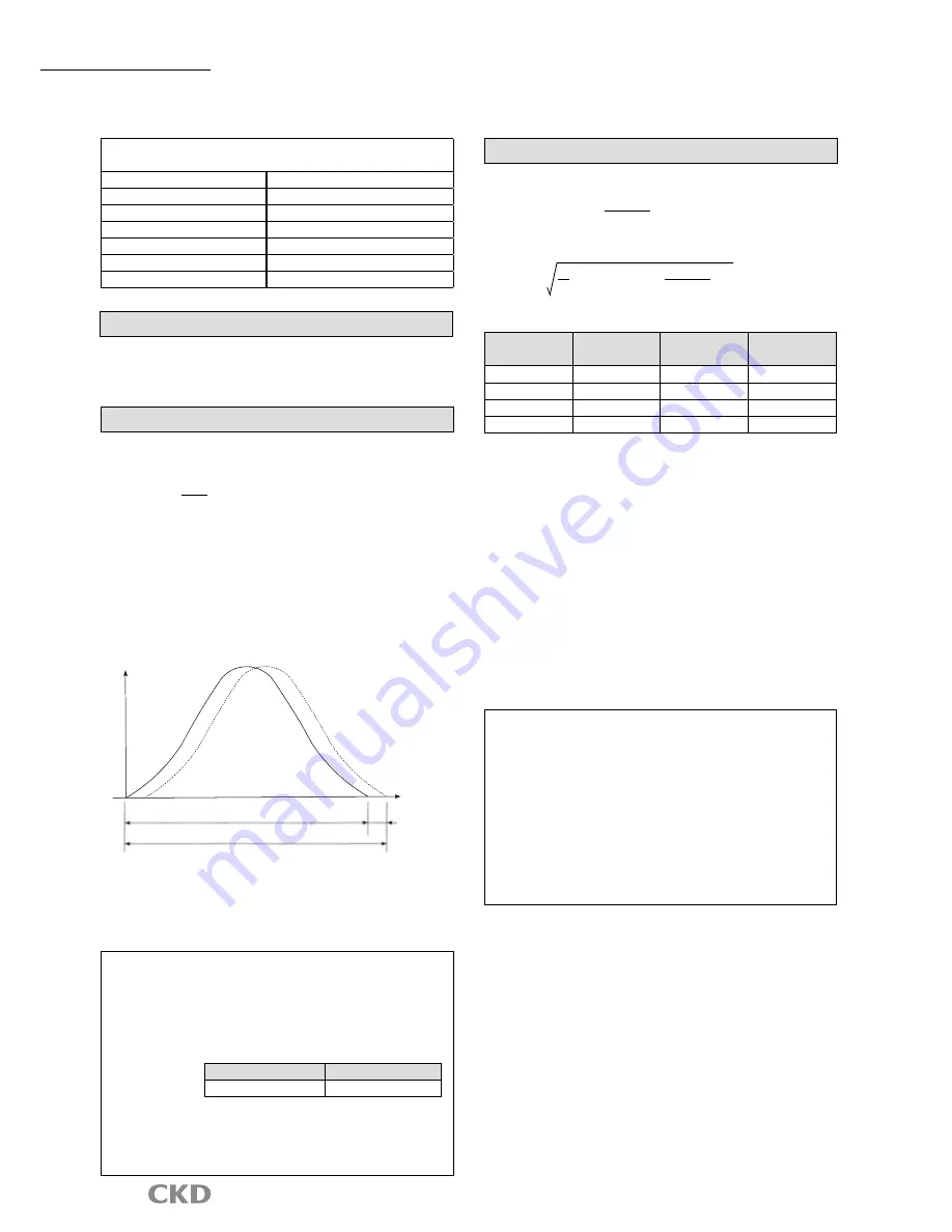
(Cautions)
Actual movement time is the direct drive actuator
command movement time plus setting.
5GVVNKPI
VKOG
Directive moving time of direct drive actuator
Actual moving time
Time
Speed
The settling time differs based on the working condition, but generally is
between 0.025 and 0.2s.
Movement time t
1
used for selecting the model should be the direct drive
actuator command movement time. The direct drive actuator command
movement time is also used for settling the movement time in the NC program.
Note: Frictional torque is applied to the output shaft due
to the bearing or sliding surface or other friction.
Friction torque is calculated with a relational formula.
Tf = μ, Ff and Rf (N•m)
Ff = m•g
μ
: Coefficient of friction
Rolling friction
Sliding friction
μ = 0.03 to 0.05
μ = 0.1 to 0.3
Ff : Force applied on sliding surface or bearings (N)
Rf : Average friction radius (m)
m : Weight (kg)
g : Gravity acceleration (m/s
2
)
. Load torque
a) The maximum load torque is obtained with the following formula.
b) The effective value of the load torque is obtained with the following formula.
Tm=[Am•(J+J
M
)•
Trms=
•fc
• (r/Am/ (J + J
M
)/
+ T
F
+ T
W
)/fc + T
MF
ψ•π
180, t
12
t
1
t
0
ψ•π
180, t
12
Vm Am r is the below table value for here.
Cam curve
V
m
A
m
r
MS
1.76
5.5
0.707
MC
1.28
8.01
0.500
MT
2.00
4.89
0.866
TR
2.18
6.17
0.77
J
M
T
MF
f is as follows.
J
M
: Output shaft moment of inertia (kg/m
2
)
T
MF
: Output shaft friction torque (N•m)
fc
: Usage factor (fc = 1.5 during normal use)
If the temporarily selected actuator does not satisfy
either of the following conditions, increase the actuator
size and calculate again.
Maximum load torque <maximum output torque
Effective value of load torque <continuous output torque
Note) The max. torque will be limited when rotating at
high speeds.
Check with the model selection software when
using at these speed ranges..
(Note) The working torque expresses, with a torque value, the
external load, etc., applied on the output shaft as a load.
Working torque TW is calculated with the following formula:
T
W
=F
W
×R
W
(N•m)
F
W
(N) : Force required for work
R
W
(m) : Radius for work
(Example)
When setting the output shaft horizontal, the table
workpiece , and jig, etc., are the working torque.


