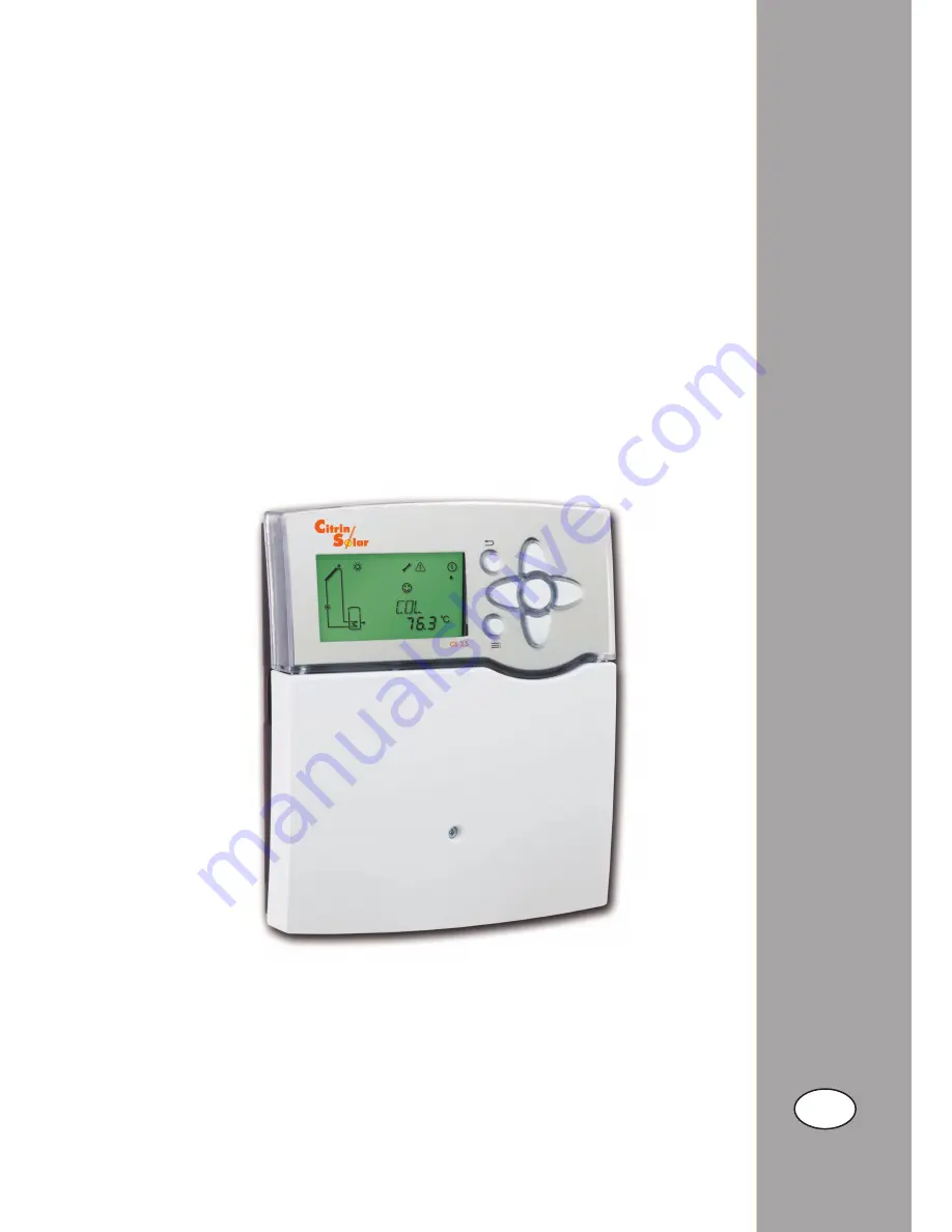
CitrinSolar CS 2.5 Mounting And Operating Instructions Download Page 1

CS 2.5

Manual

Mounting and operating instructions

Installation
Operation
Functions and options
Troubleshooting

Thank you for buying this product.
Read this manual carefully to get the best performance from this unit.
Please keep this manual carefully.


en

*11209346*

11209346

Summary of Contents for CS 2.5

Page 1: ...g instructions Installation Operation Functions and options Troubleshooting Thank you for buying this product Read this manual carefully to get the best performance from this unit Please keep this man...

Page 2: ...rrows indicate instruction steps that should be carried out WARNING Warnings are indicated with a warning triangle They contain information on how to avoid the danger described Safety advice Please pa...

Page 3: ...isuali sation 16 segment display 7 segment display 8 symbols control lamp directional pad and background illumination Operation 7 push buttons at the front of the housing Functions System controller f...

Page 4: ...Insert lower wall plugs Fasten the housing to the wall with the lower fastening screws and tighten Carry out the electrical wiring in accordance with the terminal allocation see chap 2 2 Put the cove...

Page 5: ...ors S1 to S5 to the corresponding terminals with either polarity S1 sensor 1 collector sensor S2 sensor 2 e g store sensor base S3 sensor 3 e g store sensor top S4 sensor 4 e g store sensor store 2 S5...

Page 6: ...g in a spreadsheet programme Note Do not use an SD HC card A standard SD card is not included with the CS 2 5 For more information about using an SD card see chap 6 2 page 58 SD card 2 4 SD card slot...

Page 7: ...circuit return pre heating and thermostatic afterheating page 24 Solar system with store loading in layers and heat exchange control page 25 Solar system with store loa ding in layers and thermosta t...

Page 8: ...system with east west collectors store loading in layers and and thermostatic afterheating page 39 Solar system with store loa ding in layers and east west collectors page 36 Solar system with east we...

Page 9: ...h the corresponding parameters of the function or option are available In order to activate or deactivate a function it must be selected in the menu level The display changes to the ad justment menu i...

Page 10: ...nel display consists of 2 lines The upper display line is an alphanumeric 16 segment display In this line mainly channel names and menu items are displayed In the lower 7 segment display channel value...

Page 11: ...urner operation Valve Store Store heat exchanger Store 2 or afterheating solid fuel boiler with additional symbol Upper store sensor Valve System screen in the system monitoring display If the control...

Page 12: ...ore top TST2B Temperature store 2 base TSFL Temperature solar flow TSRE Temperature solar return TSFB Temperature solid fuel boiler TSTR Temperature store return preahting TRET Temperature return S3 T...

Page 13: ...mmissioning menu consists of the channels descri bed in the following In order to make an adjustment push button 5 The set symbol flashes and the adjustment can 4 System Adjust the desired system 5 Ma...

Page 14: ...n and normally the factory settings will give close to optimum operation 6 Loading store 2 Switch on or off the loading store 2 option Note Loading store 2 can only be adjusted if a 2 store system or...

Page 15: ...54 OPARR Parallel relay option 55 OHQM Heat quantity measurement option 55 GFDS Registration Grundfos sensors 55 PRS Pressure monitoring option 57 DATE Enter date 57 Sensor Ter minal Designation Descr...

Page 16: ...mperature collector S2 TST1B Temperature store 1 base S3 TST1T Temperature store 1 top S4 TST2B Temperature store 2 top S5 Optional sensor for measurement purposes or options VFS RPS V40 Adjustment ch...

Page 17: ...Ter minal Designation Description S1 TCOL Temperature collector S2 TSTB Temperature store base S3 TSTT Temperature store top S4 Optional sensor for measurement purposes or options S5 VFS RPS V40 Adjus...

Page 18: ...op S4 Optional sensor for measurement purposes or options S5 VFS RPS V40 Relay Description R1 Solar pump R2 R4 optional Parallel relay R3 3 port valve store top base Adjustment channels Channel Descri...

Page 19: ...measurement purposes or options VFS RPS V40 Relay Description R1 Solar pump R2 R4 optional Parallel relay R3 3 port valve store 1 2 Adjustment channels Channel Description Page ARR System 45 LOAD1 Loa...

Page 20: ...urposes or options S4 TST2B Temperature store 2 base S5 Optional sensor for measurement purposes or options VFS RPS V40 Adjustment channels Channel Description Page ARR System 45 LOAD1 Loading 1 46 LO...

Page 21: ...onal sensor for measurement purposes or options RPS V40 Relay Description R1 Solar pump collector 1 R2 Solar pump collector 2 R2 R4 optional Parallel relay Adjustment channels Channel Description Page...

Page 22: ...ler S5 Optional sensor for measurement purposes or options VFS RPS V40 Relay Description R1 Solar pump R3 Loading pump solid fuel boiler R2 optional Parallel relay R4 Adjustment channels Channel Descr...

Page 23: ...erature return S5 Optional sensor for measurement purposes or options VFS RPS V40 Relay Description R1 Solar pump R2 Return preheating R3 optional Parallel relay R4 Adjustment channels Channel Descrip...

Page 24: ...4 TRET Temperature return S5 Optional sensor for measurement purposes or options VFS RPS V40 Relay Description R1 Solar pump R2 Return preheating R3 optional Parallel relay R4 Afterheating store loadi...

Page 25: ...asurement purposes or options VFS RPS V40 Relay Description R1 Solar pump R2 Heat exchange pump R3 3 port valve store top base R4 optional Parallel relay System 11 Solar system with store loading in l...

Page 26: ...S1 Temp Sensor Pt1000 L R3 R2 R1 GND S1 S2 S3 S4 S5 VBus PWM 1 PWM 2 N R4 V40 L VFS RPS out in Note 3 port valve normally open store top S3 sted maximum temperature via the valve R3 The priority logic...

Page 27: ...RPS V40 Relay Description R1 Solar pump R2 optional Parallel relay R3 Loading pump solid fuel boiler R4 3 port valve store top base Adjustment channels Channel Description Page ARR System 45 LOAD1 Lo...

Page 28: ...n S3 heat source S4 heat sink heating circuit return preheating hea ting circuit backup is possible via another valve R2 System 14 Solar system with store loading in layers and return preheating S5 R3...

Page 29: ...VBus PWM 1 PWM 2 N R4 V40 L VFS RPS out in Adjustment channels Channel Description Page ARR System 45 LOAD1 Loading 1 45 LOAD2 Loading 2 48 COL Collector 50 LLOGI Loading logic 51 COOL Cooling functi...

Page 30: ...locking protection 54 OPARR Parallel relay option 55 OHQM Heat quantity measurement option 55 Sensor Ter minal Designation Description S1 TCOL Temperature collector S2 TST1B Temperature store 1 base S...

Page 31: ...ode 54 BLPR Blocking protection 54 OPARR Parallel relay option 55 OHQM Heat quantity measurement option 55 Sensor Ter minal Designation Description S1 TCOL Temperature collector S2 TST1B Temperature s...

Page 32: ...mode 54 BLPR Blocking protection 54 OPARR Parallel relay option 55 OHQM Heat quantity measurement option 55 Sensor Ter minal Designation Description S1 TCOL1 Temperature collector 1 S2 TST1B Temperatu...

Page 33: ...Parallel relay option 55 OHQM Heat quantity measurement option 55 GFDS Registration Grundfos sensors 55 Sensor Ter minal Designation Description S1 TCOL1 Temperature collector 1 S2 TSTB Temperature s...

Page 34: ...speed 47 MAN Manual mode 54 BLPR Blocking protection 54 OPARR Parallel relay option 55 OHQM Heat quantity measurement option 55 Sensor Ter minal Designation Description S1 TCOL1 Temperature collector...

Page 35: ...47 MAN Manual mode 54 BLPR Blocking protection 54 OPARR Parallel relay option 55 OHQM Heat quantity measurement option 55 Sensor Ter minal Designation Description S1 TCOL1 Temperature collector 1 S2...

Page 36: ...ption 55 OHQM Heat quantity measurement option 55 Sensor Ter minal Designation Description S1 TCOL1 Temperature collector 1 S2 TSTB Temperature store base S3 TSTT Temperature store top S4 Optional sen...

Page 37: ...55 Sensor Ter minal Designation Description S1 TCOL1 Temperature collector 1 S2 TST1B Temperature store 1 base S3 Optional sensor for measurement purposes or options S4 TST2B Temperature store 2 base...

Page 38: ...mode 54 BLPR Blocking protection 54 OPARR Parallel relay option 55 OHQM Heat quantity measurement option 55 Sensor Ter minal Designation Description S1 TCOL1 Temperature collector 1 S2 TSTB Temperatu...

Page 39: ...protection 54 OPARR Parallel relay option 55 Sensor Ter minal Designation Description S1 TCOL1 Temperature collector 1 S2 TSTB Temperature store base S3 TSTT Temperature store top S4 Optional sensor f...

Page 40: ...erature collector 2 VFS Optional sensor for measurement purposes or options RPS V40 Relay Description R1 Solar pump collector 1 R2 Solar pump collector 2 R3 Loading pump solid fuel boiler R4 3 port va...

Page 41: ...pump Speed control of a HE pump is possible via a PWM signal For this purpose the pump has to be connected to the re lay as well as to one of the PWM outputs of the controller see page 4 In the PUMP...

Page 42: ...on BLPR1 2 3 Blocking protection active Display of blocking protection time Display of temperatures at S3 S4 and S5 Indicates the current temperature at the corresponding additional sensor without con...

Page 43: ...ours of the relay h R1 h R2 h R3 h R4 Full hours are displayed The accumulated operating hours can be set back to 0 As soon as one operating hours channel is selected the symbol is displayed In order...

Page 44: ...in the channel kWh and in MWh in the channel MWh The overall heat quantity results from the sum of both values The accumulated heat quantity can be set back to 0 As soon as one of the display channel...

Page 45: ...erence must be at least 0 5 K higher than the switch on tempe rature difference LOAD 1 2 DT 1 2 S Set temperature difference Adjustment range 1 5 50 0 K in steps of 0 5 K Factory setting 10 0 K LOAD 1...

Page 46: ...he value at S3 reaches the limit temperature the system will be switched off LOAD 1 2 S 1 2 MAXS Sensor store maximum temp Adjustment range 1 store system S2 S3 2 store system S4 S5 Factory setting 1...

Page 47: ...collector cooling is active is displayed flashing COL 1 2 OCCO 1 2 Adjustment range ON OFF Factory setting OFF Note This function is only available if the system cooling function and the heat dump fun...

Page 48: ...ws through the inactive field and only the correspon ding relay is energised Multi store systems If the tube collector function is activated the speed of the solar pump will decrease to nLO during the...

Page 49: ...eached the second store will be loaded If the temperature of the first store falls below SMAX the second store will no longer be loaded regardless of whether the switch on conditions of the priority s...

Page 50: ...e activated As soon as the adjustable spread difference DTSE between the collector and the priority store is reached the second store will be loaded in parallel unless it is blocked If the temperature...

Page 51: ...cooling function is active is shown on the display flashing System cooling CooL OSYC System cooling option Adjustment range ON OFF Factory setting OFF COOL DTCO Switch on temperature diff Adjustment r...

Page 52: ...ol Both switch on and switch off temperature differences DT3O and DT3F as well as the set temperature difference DT3S and rise RIS3 are valid Minimum temperature limitation Maximum temperature limitat...

Page 53: ...2 Selection 4 5 Factory setting 4 Return preheating DT3 S2DT3 Reference sensor Selection 3 5 Factory setting 3 In order to heat the heating circuit return by means of heat supplied by the solar circu...

Page 54: ...0 23 45 Factory setting 06 00 in steps of 15 min AH t1F Switch off time 1 Adjustment range 00 00 23 45 Factory setting 22 00 For control and service work the operating mode of the controller can be ma...

Page 55: ...rV40 or with Grundfos sensor Enable the heat quantity measurement option in the channel OHQM Select the type of flow rate detection in the channel FTYPE OHQM FTYPE Flow rate detection type Selection 1...

Page 56: ...e sensors have to be deac tivated first GFDS OFLOW Selection ON OFF Factory setting OFF HQM sensors OHQM SFHQM Flow sensor Adjustment range 1 2 3 5 Factory setting 1 If the flow rate detection type FM...

Page 57: ...splayed until the system pressure exceeds the switch off threshold factory setting 1 0 bar In the case of low pressure the message ELEAK will be displayed PRS LEAKO on at Adjustment range 0 3 5 7bar F...

Page 58: ...guage can be chosen dE German En English Fr French LANG Language Selection dE En Fr Factory setting En SD card If an SD card is used COM is shown on the display If the SD card is full COM is flashing...

Page 59: ...ector emergency temperature 1 47 OCCO1 OFF Option collector cooling 1 47 CMAX1 110 C Maximum collector temperature 1 47 OCMI1 OFF Option collector minimum limitation 1 47 CMIN1 10 C Minimum collector...

Page 60: ...change 52 DT3O 6 K Switch on difference 52 DT3F 4 K Switch off difference 52 DT3S 10 K Set difference 52 RIS3 2 K Rise 52 MAX3O 60 C Switch on temperature maximum limitation 52 MAX3F 58 C Switch off t...

Page 61: ...option 56 PRS Pressure monitoring option 57 OOVPR OFF Overpressure 57 OVPRO 5 5 bar Overpressure switch on value 57 OVPRF 5 0 bar Overpressure switch off value 57 OLEAK OFF Low pressure 57 LEAKO 0 7...

Page 62: ...em In order to authorize the access enter 0262 in the menu item CODE Channel Factory setting Adjustment range Description TIME 12 00 00 00 23 59 Time DT O 8 1 0 50 0 Switch on temperature difference s...

Page 63: ...ault Check and if necessary cor rect the connection of the sensor plugs If a sensor signal does not appear the sensor has to be replaced ERPS 9999 Error at RPS sensor ELEAK Measured minimum pressure L...

Page 64: ...the spare fuse becomes accessible when the cover is removed To replace the fuse pull the fuse holder from the base fuse WARNING Electric shock Upon opening the housing live parts are exposed Always d...

Page 65: ...ified yes Check replace it Decalcify it no Heat exchanger blocked yes no Clean it Heat exchanger too small yes Replace with correctly sized one no Plausibility control of the option tube collec tor fu...

Page 66: ...ector is considerably warmer than the store yes no Does the pump start up in manual operation yes There is no current check fuses replace them and check power supply The adjusted temperature differen...

Page 67: ...e 2 46 Low pressure 57 M Manual mode 54 Maximum speed 47 Maximum store temperature 45 Maximum temperature limitation 52 Minimum collector limitation 47 Minimum speed 47 Minimum temperature limitation...

Page 68: ...ffer a guarantee for the comple teness of the drawings and texts of this manual they only represent some examples They can only be used at your own risk No liability is assumed for incorrect incomplet...

Reviews: