


20
carefully checked. Faults such as overheating may be caused by operator habits or by overloading.
After a problem has been diagnosed and corrected, it is a good idea to clear the fault history file. This
allows the controller to accumulate a new file of faults. By checking the new history file at a later date, you
can readily determine whether the problem was indeed fixed.
Or checking the problems according to the flashing of the STATUS light on the top of the controller, please
refer to the details mentioned our service manual which is available separately.
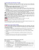
Trouble-Shooting Guide (For Series System):
Symptoms
Possible Causes
The vehicle cannot be started.
A. The controller has no power:
1. There is something wrong with the battery or wire connections.
2. The fuse to power connection is burnt.
3. The resistance for pre-charging is broken.
B. No signal is transmitted to the controller:
1. The ignition key is damaged or its wiring becomes disconnected.
2. The accelerator part of the pedal is damaged.
3. There is something wrong with acceleration pedal.
4. The polarity diode is broken or has a short.
5. The green wire connecting the acceleration pedal and the controller
KSI is disconnected.
C. The contacting point of the contactor becomes stuck.
D. The controller of the motor is damaged.
The vehicle can only move
forward and cannot be
reversed, or vice versa
1.
The switch is damaged.
2. The inserts on the commutators have become loose.
3. The commutators are damaged.
The vehicle can only run at
slow speed
Insufficient Battery
Handbrake is not engaged or brake shoe is not returning
Accelerator Defect
Controller Defect
Trouble Shooting Guide (For SEPEX System)
Please refer to Troubleshooting Chart of Curtis SEPEX controller.
Please contact your local dealer or a qualified electrician to work on the problems related to the
motor, controller or electrical system of the vehicle when you are not able to fix them.
5.5 Diagnostics and Troubleshooting
The 1268 controller provides diagnostics information to assist technicians in troubleshooting the drive
system problems. This information is displayed on the handheld programmer (or PC Programming Station),
and it is also available in the form of fault codes issued by the controller’s built-in Status LED and the
optional remote LED driven by the controller’s external LED output. Refer to the troubleshooting chart for
suggestions covering a wide range of possible faults.
Summary of Contents for Bubble Buddy
Page 5: ...5 Fig 2 Fig 3...
Page 29: ...29...