


1-2
Cisco UCS Invicta C3124SA Appliance Installation Guide
OL-31369-01
Chapter 1 Overview
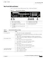
Figure 1-2 shows the rear panel features of the Cisco UCS Invicta C3124SA Appliance (identical for all
versions of the Cisco UCS Invicta C3124SA Appliance).
Figure 1-2
UCS Invicta C3124SA Appliance Rear Panel Features
Table 1-1 provides PCle Slot Descriptions
Note
A maximum of 2 interface cards are supported. PCle 2 and 5 interface card types can be different or the
same.
1
Power supplies (two)
7
1-Gb Ethernet dedicated management port
2
PCIe slot on riser 2:
PCIe 5—full-height, 3/4-length, x16 lane)
8
USB 2.0 port
3
PCIe slot on riser 2:
PCIe 4—half-height, 3/4-length, x8 lane)
9
Quad 1-Gb Ethernet ports
(LAN1, LAN2, LAN3, and LAN4)
The two left-most of these ports are the ports
used for management during configuration.
4
VGA video connector
10 PCIe slots on riser 1:
PCIe 1—full-height, half-length, x8 lane
PCIe 2—full-height, half-length, x16 lane
PCIe 3—full-height, half-length, x8 lane
5
Serial port (RJ-45 connector)
11 Rear Identification button/LED
6
USB port
–
PSU1
PSU2
PCIe 1
PCIe 2
PCIe 3
PCIe 4
PCIe 5
4
9
8
10
7
11
6
5
2
3
331826
1
Table 1-1
PCle Slot Descriptions
PCle Slot
Description
1
Netlist NVRAM Card
2
Interface Card 2
3
Not Populated
4
LSI HBA
5
Interface Card 1