S e n d d o c u m e n t c o m m e n t s t o u c s - d o c f e e d b a c k @ c i s c o . c o m
2-24
Cisco UCS 6100 Series Fabric Interconnect Hardware Installation Guide
OL-20036-02
Chapter 2 Installing the Cisco UCS 6100 Series Fabric Interconnect
Replacing or Installing Components
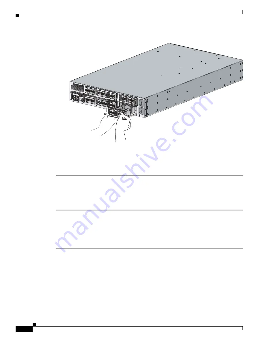
Figure 2-13
Removing an Expansion Module From the Cisco UCS 6140XP
Step 5
Place the module on an antistatic mat or antistatic foam if not immediately reinstalling it in another slot.
Step 6
If you are not installing another expansion module in its place, install a filler panel (N10-SBLKE=) to
keep dust out of the chassis and to maintain the designed airflow through the chassis. If you are installing
a replacement expansion module, see
Installing an Expansion Module, page 2-24
.
Installing an Expansion Module
To install an expansion module, follow these steps:
Step 1
Ensure that the system (earth) ground connection has been made. For ground connection instructions,
see the
“Grounding the System” section on page 2-11
.
Step 2
Grasp the handle of the module and place your other hand under the module to support it.
Step 3
Gently slide the module into the opening until you cannot push it any further.
Step 4
Tighten the captive screw on the front of the module.
Replacing or Installing Power Supplies
The Cisco UCS 6100 Series Fabric Interconnect supports two front-end power supplies, but may be used
with one power supply. If you need to replace an existing power supply, follow the procedures that
explain how to remove and install power supplies. If you are installing a new power supply where one
did not exist before, follow the installation procedure.
186598


