background image

S e n d   d o c u m e n t   c o m m e n t s   t o   u c s - d o c f e e d b a c k @ c i s c o . c o m

1-6

Cisco UCS 6100 Series Fabric Interconnect Hardware Installation Guide

OL-20036-02

Chapter 1      Product Overview

  Expansion Modules

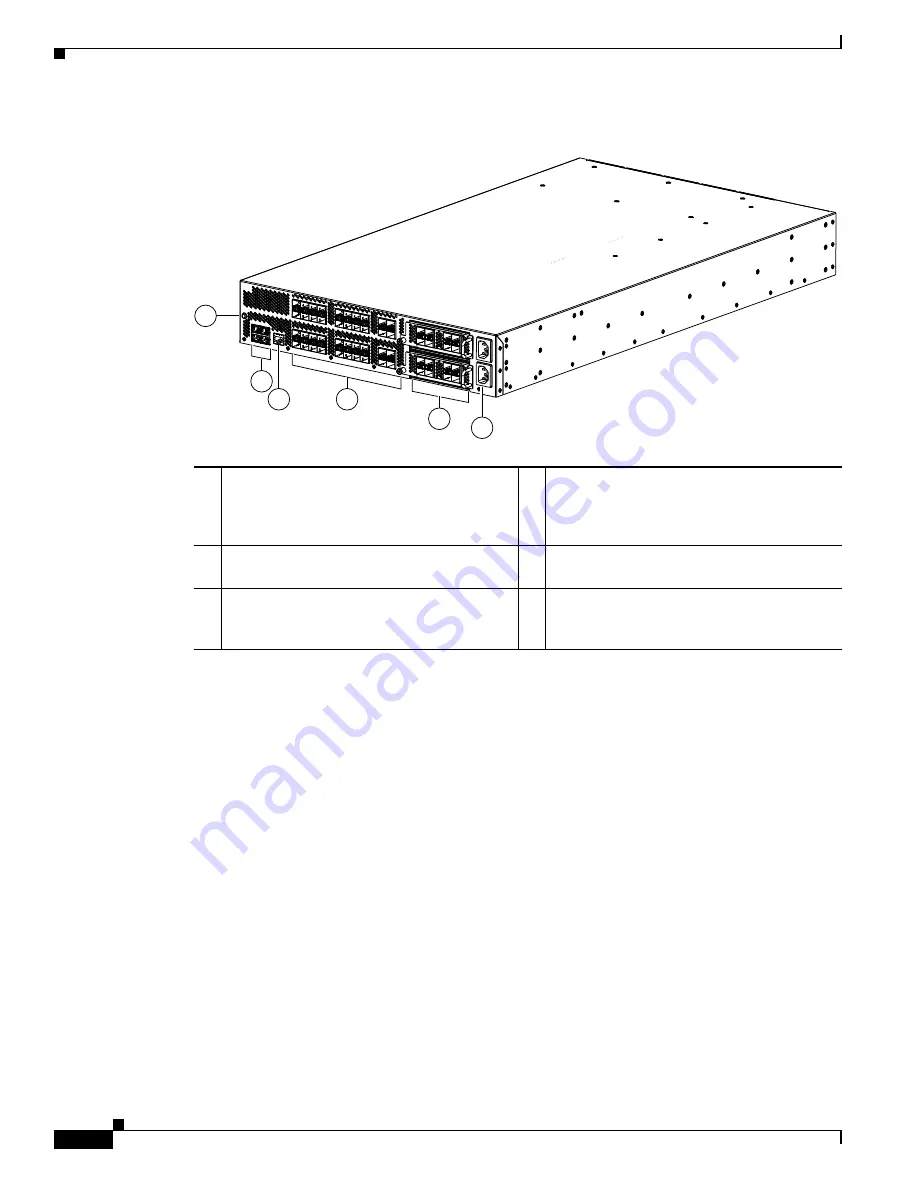
Figure 1-7

Cisco UCS 6140XP Rear View

Expansion Modules

Expansion modules allow Cisco UCS 6100 Series Fabric Interconnect to be configured as cost-effective 
10-Gigabit Ethernet fabric interconnects and as I/O consolidation platforms with native Fibre Channel 
connectivity. The Cisco UCS 6120XP has one slot for an optional uplink expansion module. The Cisco 
UCS 6140XP has two slot for an optional uplink expansion module.There are several modules that can 
be accommodated in this slot: 

  •

N10-E0440 provides 4 10G SFP+, and 4 Fibre Channel 1/2/4G SFP-based uplink connections. The 
10GE ports are encryption capable.

  •

N10-E0600 provides 6 10G SFP+ based uplink connections.

  •

N10-E0080 provides 8 1/2/4 G Fibre Channel, SFP-based uplink connection.

  •

N10-E0060 provides 6 8/4/2/1 G Fibre Channel uplink connections

The chassis supports hot swapping of the expansion modules. If the expansion modules are not in place, 
a cover plate should be used to ensure proper airflow in the chassis.

1

System status LED

2

Ethernet connector with two cross-connect 
ports on the left (top and bottom), and two 
network management ports on the right (top 
and bottom)

Console port

4

40 fixed SFP+ 10-Gigabit Ethernet ports (up 
to 16 can be 1G SFP)

5

Expansion modules, shown here with two 
4-port Fibre Channel plus 4-port 10-Gigabit 
Ethernet expansion modules

6

AC power connectors

186265

2

5

6

3

4

1

Summary of Contents for UCS 6120XP

Page 1: ... o c o m Americas Headquarters Cisco Systems Inc 170 West Tasman Drive San Jose CA 95134 1706 USA http www cisco com Tel 408 526 4000 800 553 NETS 6387 Fax 408 527 0883 Cisco UCS 6100 Series Fabric Interconnect Hardware Installation Guide January 25 2010 Part Number OL 20036 02 ...

Page 2: ...nse You can determine whether your equipment is causing interference by turning it off If the interference stops it was probably caused by the Cisco equipment or one of its peripheral devices If the equipment causes interference to radio or television reception try to correct the interference by using one or more of the following measures Turn the television or radio antenna until the interference...

Page 3: ... Overview 1 1 Interconnect Features 1 1 Cisco UCS 6120XP Chassis 1 2 Cisco UCS 6140XP Chassis 1 4 Expansion Modules 1 6 N10 E0440 1 7 N10 E0600 1 8 N10 E0080 1 8 N10 E0060 1 9 Ports 1 10 Cisco UCS 6120XP 1 10 Cisco UCS 6140XP 1 12 Power Supply 1 14 Fan Module 1 16 LED Descriptions 1 17 Port Level LEDs 1 18 Supported Transceivers 1 18 SFP Transceivers 1 18 SFP Transceivers 1 19 SFP Copper Cables 1 ...

Page 4: ... Proper Grounding Practices 2 11 Preventing Electrostatic Discharge Damage 2 13 Establishing the System Ground 2 17 Required Tools and Equipment 2 17 Grounding the Chassis 2 18 Starting the System 2 20 Replacing or Installing Components 2 21 Replacing or Installing Expansion Modules 2 22 Removing an Expansion Module 2 22 Installing an Expansion Module 2 24 Replacing or Installing Power Supplies 2 ...

Page 5: ... from an SFP Transceiver 3 9 Maintaining SFP Transceivers and Fiber Optic Cables 3 10 A P P E N D I X A System Specifications A 1 Power Specifications A 2 Transceiver Specifications A 3 Environmental Conditions and Power Requirement Specifications for SFP Transceivers A 3 General Specifications for Cisco Fibre Channel SFP Transceivers A 3 Environmental Conditions and Power Requirements Specificati...

Page 6: ... u m e n t c o m m e n t s t o u c s d o c f e e d b a ck c i s c o c o m Contents vi Cisco UCS 6100 Series Fabric Interconnect Hardware Installation Guide OL 20036 02 System Operation Best Practices D 2 I N D E X ...

Page 7: ...ollows Chapter Title Description Chapter 1 Product Overview Provides an overview of the Cisco UCS 6100 Series Fabric Interconnect and its components Chapter 2 Installing the Cisco UCS 6100 Series Fabric Interconnect Describes how to install the Cisco UCS 6100 Series Fabric Interconnect and how to install modules power supplies and fan assemblies Chapter 3 Connecting the Cisco UCS 6100 Series Fabri...

Page 8: ...stallation troubleshooting information for the Cisco UCS 6100 Series Fabric Interconnect Chapter Title Description Warning IMPORTANT SAFETY INSTRUCTIONS This warning symbol means danger You are in a situation that could cause bodily injury Before you work on any equipment be aware of the hazards involved with electrical circuitry and be familiar with standard practices for preventing accidents Use...

Page 9: ...EITSHINWEISE Dieses Warnsymbol bedeutet Gefahr Sie befinden sich in einer Situation die zu Verletzungen führen kann Machen Sie sich vor der Arbeit mit Geräten mit den Gefahren elektrischer Schaltungen und den üblichen Verfahren zur Vorbeugung vor Unfällen vertraut Suchen Sie mit der am Ende jeder Warnung angegebenen Anweisungsnummer nach der jeweiligen Übersetzung in den übersetzten Sicherheitshin...

Page 10: ...a INSTRUCCIONES IMPORTANTES DE SEGURIDAD Este símbolo de aviso indica peligro Existe riesgo para su integridad física Antes de manipular cualquier equipo considere los riesgos de la corriente eléctrica y familiarícese con los procedimientos estándar de prevención de accidentes Al final de cada advertencia encontrará el número que le ayudará a encontrar el texto traducido en el apartado de traducci...

Page 11: ...ão de prevenção de acidentes Use o número da declaração fornecido ao final de cada aviso para localizar sua tradução nos avisos de segurança traduzidos que acompanham o dispositivo GUARDE ESTAS INSTRUÇÕES Advarsel VIGTIGE SIKKERHEDSANVISNINGER Dette advarselssymbol betyder fare Du befinder dig i en situation med risiko for legemesbeskadigelse Før du begynder arbejde på udstyr skal du være opmærkso...

Page 12: ...Se n d d o c u m e n t c o m m e n t s t o u c s d o c f e e d b a ck c i s c o c o m xii Cisco UCS 6100 Series Fabric Interconnect Hardware Installation Guide OL 20036 02 Preface ...

Page 13: ...Se n d d o c u m e n t c o m m e n t s t o u c s d o c f e e d b a ck c i s c o c o m xiii Cisco UCS 6100 Series Fabric Interconnect Hardware Installation Guide OL 20036 02 Preface ...

Page 14: ...Preparation Guide Cisco UCS 5108 Server Chassis Hardware Installation Guide Regulatory Compliance and Safety Information for Cisco UCS Release Notes for Cisco UCS Manager Obtaining Documentation and Submitting a Service Request For information on obtaining documentation submitting a service request and gathering additional information see the monthly What s New in Cisco Product Documentation which...

Page 15: ...gabit Ethernet 1 2 and 4 Gbps Fibre Channel networks and provides consolidated I O connectivity to both production Ethernet LANs and Fibre Channel SANs in a cost effective high performance low latency environment The Cisco UCS 6100 series has the following characteristics Depending on the model and expansion modules used 20 to56 ports are on the back of the chassis The Cisco UCS 6120XP has 20 port...

Page 16: ... for all Ethernet LEDs Cisco UCS 6120XP Chassis The Cisco UCS 6120XP chassis is 1 RU 1 72 inches tall 17 3 inches wide and 30 0 inches deep It mounts in a standard 19 inch rack the Cisco R Series Rack is an ideal choice The chassis has two power supplies and two fan modules on the front of the chassis and it has network ports on the rear of the chassis The airflow is front to back Figure 1 2 shows...

Page 17: ...o UCS 6120XP Front View Close up The rear of the Cisco UCS 6120XP chassis has 20 fixed 10 Gigabit Fiber Channel over Ethernet capable SFP Ethernet ports 1 slot for an optional expansion module an Ethernet connector with 2 cross connect ports and 2 management ports a console port and 2 AC power connectors Up to eight of the 20 ports can be 1Gbps SFP ports if necessary Figure 1 4 shows the rear of t...

Page 18: ...unts in a standard 19 inch rack the Cisco R Series Rack is an ideal choice The chassis has two power supplies and two fan modules on the front of the chassis and it has network ports on the rear of the chassis The airflow is front to back Figure 1 5 shows the front of the Cisco UCS 6140XP 1 System status LED 2 Ethernet connector with two cross connect ports on the left top and bottom and two netwo...

Page 19: ...re 1 6 Cisco UCS 6140XP Front View Close up The rear of the Cisco UCS 6140XP chassis has 40 fixed 10 Gigabit FCoE capable Ethernet ports 2 slots for an optional expansion module an Ethernet connector with 2 cross connect ports and 2 management ports a console port and 2 AC power connectors Up to sixteen of the 40 ports can be 1Gbps SFP ports if necessary Figure 1 4 shows the rear of the Cisco UCS ...

Page 20: ...ed in this slot N10 E0440 provides 4 10G SFP and 4 Fibre Channel 1 2 4G SFP based uplink connections The 10GE ports are encryption capable N10 E0600 provides 6 10G SFP based uplink connections N10 E0080 provides 8 1 2 4 G Fibre Channel SFP based uplink connection N10 E0060 provides 6 8 4 2 1 G Fibre Channel uplink connections The chassis supports hot swapping of the expansion modules If the expans...

Page 21: ...plus Ethernet expansion module is a field replaceable unit FRU Figure 1 8 shows the Fibre Channel plus Ethernet expansion module Figure 1 8 N10 E0440 Expansion Module Figure 1 9 shows the front of the Fibre Channel plus Ethernet expansion module and shows how ports are numbered on the Fibre Channel plus Ethernet expansion module Figure 1 9 Front of the N10 E0440 Expansion Module 186384 1 Four 10 G...

Page 22: ...odule Figure 1 10 N10 E0600 Expansion Module See Figure 1 15 for an illustration of how ports are grouped and numbered on the Ethernet expansion module N10 E0080 The N10 E0080 expansion module supports 8 1 2 4G Fibre Channel SFP based uplink connection Figure 1 11 shows the N10 E0080 expansion module Figure 1 12 shows LED and port locations for the N10 E0080 expansion module Figure 1 11 N10 E0080 ...

Page 23: ...dules Figure 1 12 Front of the N10 E0080 Expansion Module N10 E0060 The N10 E0060 expansion module supports 6 1 2 4 8 G Fibre Channel SFP based uplink connections Figure 1 11 shows the N10 E0060 expansion module Figure 1 12 shows LED and port locations for the N10 E0060 expansion module Figure 1 13 N10 E0060 Expansion Module 1 Eight 1 2 4 Gbps Fibre Channel ports 2 Module LED 189954 2 1 2 3 4 5 6 ...

Page 24: ... of ports are numbered based on their function The ports are numbered top to bottom and left to right Cisco UCS 6120XP There are 20 to 28 ports on the Cisco UCS 6120XP depending on which expansion module is installed The fixed ports form group 1 and are named 1 port_number Ports 1 through 16 are unencrypted Ethernet ports Of these ports 1 through 8 are 10 Gigabit Ethernet and 1 Gigabit Ethernet ca...

Page 25: ...unction with the N10 E0600 expansion module installed Figure 1 16 Port Numbering of the Cisco UCS 6120XP Configured with the N10 E0600 Expansion Module A Group 1 ports 1 through 8 10 Gigabit or 1 Gigabit Ethernet capable unencrypted ports D Group 2 ports 1 through 4 Encrypted Ethernet ports B Group 1 ports 1 through 16 Unencrypted Ethernet ports E Group 2 ports 5 through 8 Fibre Channel ports C Gr...

Page 26: ...re 10 Gigabit Ethernet and 1 Gigabit Ethernet capable ports Ports 33 through 40 are encryption capable Ethernet ports Group 2 includes the ports in the top most expansion module Group 2 ports 1 through 4 are encrypted Ethernet ports Group 2 ports 5 through 8 are Fibre Channel ports Group 3 includes the ports in the bottom most expansion module Group 3 ports 1 through 4 are encrypted Ethernet ports...

Page 27: ...fixed ports and the Fibre Channel plus Ethernet expansion module ports Figure 1 19 Port Numbering of the Cisco UCS 6140XP Configured with the N10 E0080 Expansion Module A Group 1 ports 1 through 16 10 Gigabit Ethernet capable unencrypted ports D Groups 2 and 3 ports 1 through 4 Encrypted Ethernet ports B Group 1 ports 1 through 32 Unencrypted Ethernet ports E Groups 2 and 3 ports 5 through 8 Fibre...

Page 28: ...but the fabric interconnect is fully functional with one power supply Figure 1 21 shows the 550 W power supply which has two LEDs one for power status and one for failure condition Figure 1 22 shows the 750 W power supply which has two LEDs one for power status and one for failure condition A Group 1 ports 1 through 16 10 Gigabit or 1 GigabitEthernet capable Encrypted ports D Groups 2 and 3 ports ...

Page 29: ...D indicates a failure condition 2 Green power LED indicates the power status 1 2 189955 1 Green power LED indicates the power status 2 Amber fail LED indicates a failure condition 1 2 186264 Table 1 3 Power Supply LED Descriptions Power Supply Condition Power LED Status Fail LED Status No AC power to all power supplies Off Off Power supply failure including over voltage over current over temperatu...

Page 30: ...re 1 23 Blank Power Supply Filler Panel N10 S1BLKP Shown Fan Module TheCisco UCS 6120XP fabric interconnect has slots for two fan modules Each fan module houses 6 fans The combination of 6 fans per module and 2 modules provides the chassis with 12 fans Figure 1 24 shows the fan module for the Cisco UCS 6120XP Figure 1 24 Cisco UCS 6120XP Fan Module N10 FAN1 AC present 3 3 voltage standby VSB on an...

Page 31: ...icates a fan failure LED Descriptions Table 1 4 describes the LEDs 1 Fan module LED 1 186263 Table 1 4 LEDs for the Cisco UCS 6120XP and Cisco UCS 6140XP LED Location Color Description System Status Front of chassis Green System is operating normally Green blinking Standby Amber blinking Over temperature or major alarm Off System is powered off Fan tray Fan trays front of chassis Green Fan tray is...

Page 32: ...the electrical interface and duplex LC connector on the optical interface Table 1 6 lists the supported SFP optical transceivers Power supply Failure Power supply front of chassis Amber Power supply failure such as over voltage over current fan failure or over temperature Amber blinking Power supply is working with a warning condition such as high temperature high power or slow fan Off No warning ...

Page 33: ...es SFP 10G LR is supported between fabric interconnect and I O Module but the 300m limit still applies SFP Copper Cables Copper cables are available for use with the 10 Gigabit Ethernet SFP module See Table 1 8 for a description of these cables SFP Fibre Channel Transceivers The Cisco UCS 61oo series fabric interconnects support multimode 850nm 4Gbps SFPs with 150m reach see Table 1 9 Table 1 7 Su...

Page 34: ...c o c o m 1 20 Cisco UCS 6100 Series Fabric Interconnect Hardware Installation Guide OL 20036 02 Chapter 1 Product Overview Supported Transceivers Note The maximum length of fiber optic runs is limited to 300 meters This is imposed by our use of 802 3X 802 1Qbb Priority Pauses ...

Page 35: ...vice the system read the Regulatory Compliance and Safety Information for the Cisco UCS for important safety information Warning IMPORTANT SAFETY INSTRUCTIONS This warning symbol means danger You are in a situation that could cause bodily injury Before you work on any equipment be aware of the hazards involved with electrical circuitry and be familiar with standard practices for preventing acciden...

Page 36: ... Cisco UCS 6120XP Chassis in a Cabinet or Rack section on page 2 6 Airflow Considerations Airflow through the Cisco UCS 6100 Series Fabric Interconnect is from front to back Air enters the chassis through the fan trays and power supplies mounted at the front of the chassis and exits the chassis through perforations on the rear of the chassis To ensure proper airflow follow these guidelines Maintai...

Page 37: ...ailable for use in a cabinet See the Jumper Power Cord section on page B 8 Ensure that the chassis is adequately grounded If the chassis is not mounted in a grounded rack we recommend connecting both the system ground on the chassis and the power supply ground to an earth ground Ensure that the site power meets the power requirements listed in Appendix A Technical Specifications If available you c...

Page 38: ...992 See the Requirements Specific to Perforated Cabinets section on page 2 5 The Cisco R Series Rack is an ideal choice The cabinet or rack must also meet the following requirements The minimum vertical rack space per Cisco UCS 6120XP chassis must be one RU rack unit equal to 1 75 in 4 4 cm The minimum vertical rack space per Cisco UCS 6140XP chassis must be two RU rack unit equal to 3 5 in 8 8 cm...

Page 39: ... open rack no side panels or doors ensure that the rack meets the following requirements The minimum vertical rack space per chassis must be one RU rack unit equal to 1 75 in 4 4 cm The horizontal distance between the chassis and any adjacent chassis should be 6 in 15 2 cm and the distance between the chassis air vents and any walls should be 2 5 in 6 4 cm The Cisco RSeries racks meet or exceed al...

Page 40: ... representative immediately To inspect the shipment follow these steps Step 1 Compare the shipment to the equipment list provided by your customer service representative and verify that you have received all items including the following Print documentation Grounding lug kit Rack mount kit ESD wrist strap Cables with connectors Any optional items ordered Step 2 Check for damage and report any disc...

Page 41: ... rack mount guides on the chassis as follows a Position one of the rack mount brackets against the side of the chassis and align the screw holes See Figure 2 1 b Attach the bracket to the chassis with two of the flat head M4 screws c Repeat with the other rack mount bracket on the other side of the chassis Step 3 Attach the slider rails to the rack Use 2 12 24 screws or 2 10 32 screws depending on...

Page 42: ...tabilize the chassis in the rack by attaching the front rack mount brackets to the front rack mounting rails a Insert 2 screws 12 24 or 10 32 depending on rack type through the cage nuts and the holes in one of the front rack mount brackets and into the threaded holes in the rack mounting rail b Repeat for the front rack mount bracket on the other side of the chassis Installing the Cisco UCS 6140X...

Page 43: ...CS 6140XP Step 2 Install the rack mount guides on the chassis as follows a Position one of the rack mount brackets against the side of the chassis and align the screw holes See Figure 2 3 b Attach the bracket to the chassis with two of the flat head M4 screws c Repeat with the other rack mount bracket on the other side of the chassis Step 3 Attach the slider rails to the rack Use 2 12 24 screws or...

Page 44: ...de of the chassis with the slider rails installed in the rack Slide the rack mount glides onto the slider rails and then gently slide the chassis all the way into the rack If the chassis does not slide easily try realigning the rack mount glides on the slider rails See Figure 2 5 Figure 2 5 Sliding the Chassis Into the Rack Step 5 Stabilize the chassis in the rack by attaching the front rack mount...

Page 45: ...and includes the following topics Proper Grounding Practices page 2 11 Preventing Electrostatic Discharge Damage page 2 13 Establishing the System Ground page 2 17 Proper Grounding Practices Grounding is one of the most important parts of equipment installation Proper grounding practices ensure that the buildings and the installed equipment within them have low impedance connections and low voltag...

Page 46: ...and industrial equipment such as welding Medium to high Best grounding recommendations must be closely followed Existing commercial building is not subject to natural environmental noise or man made industrial noise This building contains a standard office environment This installation has a history of malfunction due to electromagnetic noise Medium Determine source and cause of noise if possible ...

Page 47: ...ips or alligator clips All Cisco UCS 6100 Series Fabric Interconnect chassis are equipped with a banana plug connector identified by the ground symbol next to the connector somewhere on the front panel We recommend that you use a personal ESD grounding strap equipped with a banana plug If you choose to use the disposable ESD wrist strap supplied with most field replaceable units or an ESD wrist st...

Page 48: ... that any built up static charge is then safely dissipated to the entire rack Step 3 Attach the ESD strap to the system ground in one of the following ways If you are using a wrist strap that is equipped with a plug insert the plug into an open screw hole used for the grounding lug as shown in Figure 2 7 Figure 2 7 Plugging the ESD Wrist Strap to the Cisco UCS 6120XP System Ground If you are using...

Page 49: ...ric Interconnect Grounding the System Figure 2 8 Attaching the ESD Wrist Strap to the Cisco UCS 6120XP System Ground Lug Screw 1 Open the clip by pressing its handles together 2 Side view of the clip being attached to one of the screws holding the grounding lug to the chassis 3 Back view of the clip attached to the clip attached to the grounding screw 4 Side view of the clip attached to the ground...

Page 50: ...ide enough to fit directly over the head of the lug screw or the lug barrel If you are using an ESD wrist strap that is equipped with an alligator clip attach the alligator clip directly over the head of the system ground lug screw or to the system ground lug barrel In addition follow these guidelines when handling modules Handle carriers by available handles or edges only avoid touching the print...

Page 51: ...stem power ground connections that you make The system ground connection is required if this equipment is installed in a U S or European Central Office You must connect both the NEBS ground connection and the power supply ground connection to an earth ground The NEBS ground connection is required if this equipment is installed in a U S or European Central Office You do not need to power down the c...

Page 52: ... UCS 6140XP Warning When installing or replacing the unit the ground connection must always be made first and disconnected last Statement 1046 Caution We recommend grounding the chassis even if the rack is already grounded Caution All power supplies must be grounded The receptacles of the AC power cables used to provide power to the chassis must be the grounding type and the grounding conductors s...

Page 53: ...ovided on the chassis for attaching a grounding lug The ground lug must be NRTL listed In addition the copper conductor wires must be used and the copper conductor must comply with NEC code for ampacity To attach the grounding lug and cable to the chassis follow these steps Step 1 Use a wire stripping tool to remove approximately 0 75 inches 19 mm of the covering from the end of the grounding cabl...

Page 54: ...n on page 3 1 Warning When installing or replacing the unit the ground connection must always be made first and disconnected last Statement 1046 Warning The plug socket combination must be accessible at all times because it serves as the main disconnecting device Statement 1019 To power up the fabric interconnect and verify hardware operation follow these steps Step 1 Verify that empty power suppl...

Page 55: ...ep 9 After the system boots verify that the LED operation is as follows Fan module Status LED is green Power supply Status LED is green After initialization the system status LED is green indicating that all chassis environmental monitors are reporting that the system is operational If this LED is orange or red one or more environmental monitor is reporting a problem The Link LEDs for the Ethernet...

Page 56: ...g or Installing Expansion Modules page 2 22 Replacing or Installing Power Supplies page 2 24 Replacing a Fan Module page 2 27 Removing a Cisco UCS 6120XP page 2 29 Caution To prevent ESD damage wear grounding wrist straps during these procedures and handle modules by the carrier edges only Replacing or Installing Expansion Modules You can either replace existing expansion modules or install new on...

Page 57: ...em earth ground connection has been made For ground connection instructions see the Grounding the System section on page 2 11 Step 2 Disconnect any network interface cables attached to the module Step 3 Loosen the captive screw on the module Step 4 Remove the module from the chassis by grasping the handle on the right side of the module and sliding the module part of the way out of the slot Place ...

Page 58: ...stalling an Expansion Module page 2 24 Installing an Expansion Module To install an expansion module follow these steps Step 1 Ensure that the system earth ground connection has been made For ground connection instructions see the Grounding the System section on page 2 11 Step 2 Grasp the handle of the module and place your other hand under the module to support it Step 3 Gently slide the module i...

Page 59: ...es the following topics Removing a Power Supply page 2 25 Installing a Power Supply page 2 26 Removing a Power Supply Caution If you are using the Cisco UCS 6100 Series Fabric Interconnect with one power supply removing the power supply causes the system to shut down If you are using two power supplies and you remove one of them the system continues to operate To remove a power supply follow these...

Page 60: ...the Power Supply for the Cisco UCS 6120XP Figure 2 15 Removing the Power Supply for the Cisco UCS 6140XP Step 4 Place your right hand under the power supply to support it while you slide it out of the chassis Step 5 If you are not replacing the power supply install a blank power supply filler panel N10 S1BLKP or N10 S2BLKP If you are replacing the power supply see Installing a Power Supply page 2 ...

Page 61: ...nd of the power cable to an AC power source Caution In a system with dual power supplies connect each power supply to a separate power source In case of a power source failure the second source will most likely still be available Step 6 Verify power supply operation by checking that the power supply LED is green Fan Modules The fan module N10 FAN1 or N10 FAN2 is designed to be removed and replaced...

Page 62: ... antistatic bag Step 5 Hold the replacement fan module with the LED at the bottom Step 6 Place the fan module into the front chassis cavity so it rests on the chassis and then push the fan module into the chassis as far as it can go and the captive screw makes contact with the chassis and tighten the captive screw See Figure 2 16 Step 7 Listen for the fans if the system is powered on You should im...

Page 63: ...Manager to shut down the OS on all servers in the UCS instance Graceful shutdown of a blade server is discussed in the System Management section Managing Blade Servers chapter of the UCS Manager configuration guide for your software release The related CLI commands are UCS A scope org UCS A org scope service profile service profile name UCS A org service profile power down 2 Disable the Smart Call...

Page 64: ... If the front of the chassis is unfastened from the rack and the chassis slides forward on the slider rails it may slip off the end of the rails and fall out of the rack To physically remove the Cisco UCS 6140XP from a rack follow these steps Step 1 Ensure that the weight of the Cisco UCS 6140XP is fully supported and that the chassis is being held by another person Step 2 Remove the two screws ho...

Page 65: ...n Ethernet Port page 3 3 Connecting to a Fibre Channel Port page 3 7 Preparing for Network Connections When preparing your site for network connections to the Cisco UCS 6100 Series Fabric Interconnect consider the following for each type of interface and gather all the required equipment before connecting the ports Cabling required for each interface type Distance limitations for each signal type ...

Page 66: ...re powering on the system or after the system has completed the boot process Figure 3 1 shows how to connect to the console port on the Cisco UCS 6120XP Figure 3 2 shows how to connect to the console port on the Cisco UCS 6140XP Figure 3 1 Connecting to the Console Port on a Cisco UCS 6120XP Figure 3 2 Connecting to the Console Port on a Cisco UCS 6140XP You can use the console port to perform the...

Page 67: ... 9 connector to the computer serial port Note For configuration instructions see the Cisco UCS Manager CLI Configuration Guide Connecting to the Ethernet Connector Port Caution To prevent an IP address conflict do not connect the management port to the network until the initial configuration is complete For configuration instructions see the Cisco UCS Manager GUI Configuration Guide The Ethernet c...

Page 68: ...ions for use Step 2 Remove the dust cover from the port cage Step 3 Remove the dust cover from the port end of the transceiver Step 4 Insert the transceiver into the port If the transceiver has a Mylar tab position the transceiver with the tab on the bottom and then gently insert the transceiver into the port until it clicks into place If the transceiver has a bale clasp position the transceiver w...

Page 69: ... inward and upward into the cage Next lower the bale clasp and pull the SFP transceiver straight out with a slight upward lifting force Be careful not to damage the port cage during this process Step 4 Insert a dust cover into the port end of the transceiver and place the transceiver on an antistatic mat or into a static shielding bag if you plan to return it to the factory Step 5 If another trans...

Page 70: ...ble has been released before continuing To remove the cable follow these steps Step 1 Attach an ESD wrist strap and follow its instructions for use Step 2 Press the release latch on the cable grasp the connector near the connection point and gently pull the connector from the transceiver Step 3 Insert a dust plug into the cable end of the transceiver Step 4 Insert a dust plug onto the end of the c...

Page 71: ...P transceiver can shorten its life Do not remove and install transceivers more often than necessary We recommend that you disconnect cables before installing or removing SFP transceivers to prevent damage to the cable or transceiver This section describes the proper method for installing and removing an SFP transceiver This section includes the following topics Installing an SFP Transceiver page 3...

Page 72: ...m the transceiver c Insert a dust plug into the cable end of the transceiver Caution If the transceiver does not remove easily in the next step push the transceiver completely in and then ensure that the latch is in the correct position before continuing Step 3 Remove the transceiver from the port If the transceiver has a Mylar tab latch gently pull the tab straight out do not twist and then pull ...

Page 73: ...talling a Cable into an SFP Transceiver page 3 9 Removing a Cable from an SFP Transceiver page 3 9 Installing a Cable into an SFP Transceiver Caution To prevent possible damage to the cable or transceiver install the transceiver in the port before installing the cable in the transceiver To install a cable into a transceiver follow these steps Step 1 Attach an ESD wrist strap and follow its instruc...

Page 74: ...intain high signal accuracy and prevent damage to the connectors Attenuation loss of light is increased by contamination and should be below 0 35 dB Consider the following maintenance guidelines SFP transceivers are static sensitive To prevent ESD damage wear an ESD wrist strap that is connected to the chassis Do not remove and insert a transceiver more often than is necessary Repeated removals an...

Page 75: ...ecifications Table A 1 lists the specifications for the fabric interconnects Table A 1 Physical Specification Description Specification Physical Cisco UCS 6120XP Dimensions H x W x D 1 72 in 4 4 cm x 17 3 in 43 9 cm x 30 0 in 76 2 cm Weight with two power supplies and one expansion module installed 35 lb 15 875 kg Physical Cisco UCS 6140XP Dimensions H x W x D 3 47 in 8 8 cm x 17 3 in 43 9 cm x 30...

Page 76: ...0 Hz nominal Range 47 to 63 Hz AC input current 7 5 Amps 90 VAC Maximum Input VA 675 VA 90 VAC Maximum output power per power supply 550 W 12 V up to two power supplies Maximum inrush current 35 A sub cycle duration Maximum Heat Output 1876 BTU hr Maximum hold up time 12 ms Power supply output voltage 12 VDC Efficiency Rating 87 Table A 3 Specifications for the Cisco UCS 6140XP 750W Power Supply N...

Page 77: ...ceivers Table A 6 lists the general specifications for Cisco Fibre Channel SFP transceivers at 4 Gbps Table A 4 General Specifications for the 10 Gigabit Ethernet SFP Transceiver Module Description Short Range Connector type LC Wavelength 850 nm Core size Cable distance 50 microns 300 m 62 5 microns 33 m Table A 5 Environmental Conditions and Power Requirement Specifications for the 10 Gigabit Eth...

Page 78: ...ironmental Conditions and Power Requirements Specifications for SFP Transceivers Parameter Symbol Minimum Maximum Storage temperature1 1 Absolute maximum ratings are those values beyond which damage to the device may occur if these limits are exceeded for other than a short period of time TS 40 C 40 F 85 C 185 F Case temperature1 2 2 Functional performance is not intended device reliability is not...

Page 79: ...ds and Plugs page B 3 Jumper Power Cord page B 8 Accessory Kit for the Cisco UCS Fabric Interconnect The Cisco UCS 6120XP 20 Port Fabric Interconnect accessory kit includes the following items 2 slider rails 2 rack mount guides 2 rack mount brackets 12 M4 x 0 7 x 8 mm Phillips countersunk screws 10 10 32 rack nuts 10 10 32 x 3 4 inch Phillips pan head screws 1 console cable with an RJ 45 RS 232 ad...

Page 80: ...232 console see Figure B 1 Figure B 1 Console Cable Table B 1 lists the pinouts for the RJ 45 connector on the console cable Console Port The console port is an asynchronous RS 232 serial port with an RJ 45 connector Table B 2 lists the pinouts for the console port on the Cisco UCS 6100 Series Fabric Interconnects 187491 Table B 1 Cable Connector Pinouts Signal Name P1 P1 45 Pins P2 DB 9 Pins Sign...

Page 81: ...connector on the end that plugs into an IEC C19 outlet receptacle Note Only the regular power cords or jumper power cords provided with the chassis are supported Table B 3 lists the power cords for the Cisco UCS 6100 Series Fabric Interconnects and provides their lengths in feet and meters 5 GND 6 RxD 7 DSR 8 CTS Table B 2 Console Port Pinouts continued Pin Signal Table B 3 Power Cords for the Cis...

Page 82: ... MP232 Plug Switzerland 8 2 2 5 Figure B 9 CAB 9K10A UK Power Cord 250 VAC 10 A BS1363 Plug 13 A fuse United Kingdom 8 2 2 5 Figure B 10 CAB AC 250V 13A Power Cord 250 VAC 13 A IEC60320 Plug North America 6 6 2 0 Figure B 11 CAB N5K6A NA Power Cord 250 VAC 13 A NEMA 6 15 Plug North America 8 2 2 5 Figure B 12 CAB C13 C14 JMPR Cabinet Jumper Power Cord 250 VAC 13 A C13 C14 Connectors 2 2 0 7 Figure...

Page 83: ...ications Supported Power Cords and Plugs Figure B 3 CAB 9K10A AU Figure B 4 SFS 250V 10A CN Figure B 5 CAB 9K10A EU Plug EL 206 A S 3112 2000 Cordset rating 10 A 250 V 500V Length 2500mm 186581 Connector EL 701C IEC 60320 C15 Cordset rating 10A 250V 2500 mm Plug EL 218 CCEE GB2009 186573 Connector EL 701 IEC60320 C13 Connector VSCC15 Cordset rating 10A 16 A 250 V Length 8 ft 2 in 2 5 m Plug M2511 ...

Page 84: ...ications Supported Power Cords and Plugs Figure B 6 SFS 250V 10A ID Figure B 7 SFS 250V 10A IS Figure B 8 CAB 9K10A IT OVE Cordset rating 16A 250V 2500mm Plug EL 208 187490 Connector EL 701 Cordset rating 10A 250V 500V MAX 2500 mm Plug EL 212 SI 32 186574 Connector EL 701B IEC60320 C13 EL 212 16A 250V Plug I 3G CEI 23 16 Connector C15M EN60320 C15 Cordset rating 10 A 250 V Length 8 ft 2 in 2 5 m 1...

Page 85: ...orted Power Cords and Plugs Figure B 9 CAB 9K10A SW Figure B 10 CAB 9K10A UK Figure B 11 CAB AC 250V 13A Plug MP232 R Cordset rating 10 A 250 V Length 2500mm 186578 Connector VSCC15 BKR Plug Cordset rating 10 A 250 V 500 V MAX Length 2500mm 186580 Connector EL 701C EN 60320 C15 EL 210 BS 1363A 13 AMP fuse Cordset rating 13A 250V 6 6 feet 79 2m Plug EL312MoldedTwistlock NEMA L6 20 186568 Connector ...

Page 86: ...3 shows the plug connector on the optional jumper power cord for the Cisco UCS 6100 Series Fabric Interconnects The plug plugs in to the Cisco UCS 6100 Series Fabric Interconnects power supply while the connector plugs into the receptacle of a power distribution unit for a cabinet Figure B 13 CAB C13 C14 JMPR Jumper Power Cord Cordset rating 10 A 250 V Length 8 2 ft 186570 Plug NEMA 6 15P Connecto...

Page 87: ...oftware configuration and management information refer to the Cisco UCS Manager CLI Configuration Guide or the Cisco UCS Manager GUI Configuration Guide Site Preparation Checklist Planning the location and layout of your equipment is essential for successful system operation ventilation and accessibility Table C 1 lists the site planning tasks that we recommend completing before installing the Cis...

Page 88: ...rature Humidity Altitude Atmospheric contamination Air flow 3 Power evaluation Input power type Power receptacles1 Receptacle proximity to the equipment Dedicated circuit for power supply Dedicated separate circuits for redundant power supplies UPS2 for power failures 1 Verify that the power supply installed in the chassis has a dedicated AC source circuit 2 UPS uninterruptible power supply 4 Grou...

Page 89: ...ce Records Contact and Site Information Contact and Site Information Use the following worksheet Table C 2 to record contact and site information 3 EMI electromagnetic interference 4 RFI radio frequency interference Table C 2 Contact and Site Information Contact person Contact phone Contact e mail Building site name Data center location Floor location Address line 1 Address line 2 City State Zip c...

Page 90: ...about the chassis and modules Contract Number_______________________________________________ Chassis Serial Number___________________________________________ Product Number________________________________________________ Note The supervisor module and the interface module are not removable Table C 3 Network Related Information System IP address System IP netmask Hostname Domain name IP broadcast a...

Page 91: ...hat it should be doing Because a startup problem can usually be attributed to a single component it is more efficient to isolate the problem to a subsystem rather than troubleshoot each separate component in the system Problems with the initial power up are often caused by a module that is not firmly connected to the backplane or a power supply that has been disconnected from the power cord connec...

Page 92: ... site before installing the chassis Verify that you have the appropriate power supplies for your chassis configuration Install the chassis following the rack and airflow guidelines presented in this guide Verify that the chassis is adequately grounded Initialization Best Practices When the initial system boot is complete verify the following Power supplies are supplying power to the system Fan mod...

Page 93: ...on equipment required 2 5 guidelines 2 3 screw torques 2 3 Cisco 1 2 1 4 Cisco Nexus 5020 switch fan module 1 17 port grouping 1 12 Cisco UCS 6100 features 1 1 Cisco UCS 6100 Series connecting a system ground 2 17 installing in a cabinet 2 6 2 8 installing in a rack 2 6 2 8 powering up 2 20 power supply 1 14 system ground location figure 2 18 2 19 Cisco UCS 6100 series description 1 1 Cisco UCS 61...

Page 94: ...2 24 N10 E0060 1 9 N10 E0080 1 8 N10 E0440 1 7 N10 E0600 port numbering 1 7 removing 2 22 F fan modules description 1 16 LED descriptions 1 17 removing 2 26 fiber optic cables maintaining 3 10 Fibre Channel plus Ethernet expansion module port numbering figure 1 7 Fibre Channel ports connecting 3 7 G grounding attaching the ESD wrist strap 2 13 attaching the ESD wrist strap to the system ground fig...

Page 95: ...2 6 2 8 rack mount installation 2 7 2 9 rack mount kit contents 2 6 2 8 records chassis serial number C 4 contact and site information C 3 site planning and maintenance C 1 required equipment chassis installation 2 5 RJ 45 connector pinouts B 2 S screw torques 2 3 SFP transceivers installing 3 4 installing a cable 3 5 maintaining 3 6 removing 3 4 removing a cable 3 6 specifications A 3 SFP transce...

Page 96: ...Se n d d o c u m e n t c o m m e n t s t o u c s d o c f e e d b a ck c i s c o c o m Index IN 4 Cisco UCS 6100 Series Fabric Interconnect Hardware Installation Guide OL 20036 02 ...

Reviews: