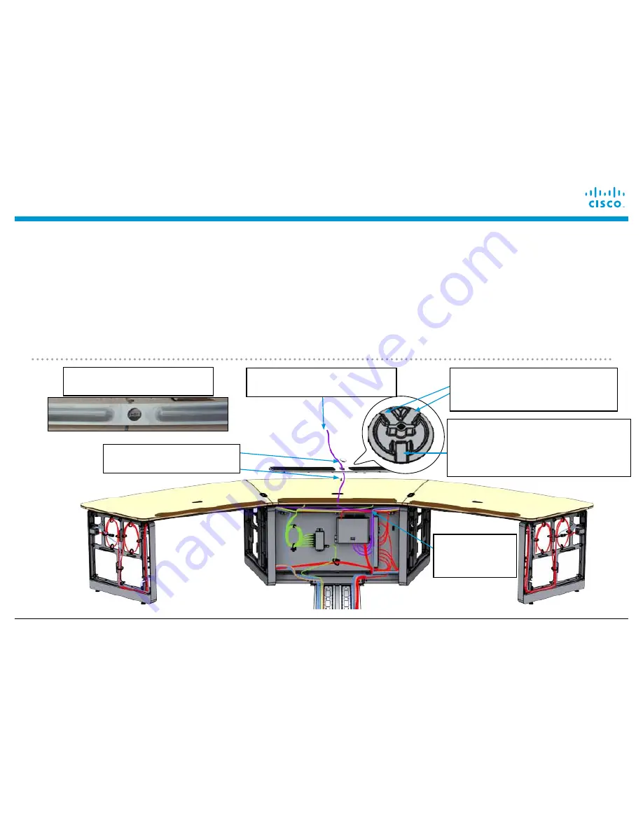
Completing Installation of the First Row Table
Page 110
© 2015 Cisco Systems, Inc. All rights reserved.
6a
Prepare the Ethernet cables for the Touch 10 devices.
a.
Remove the protective film around the center
of the mic bar.
b.
Take the Ethernet cable(s) (either one or two cables, depending on the number of
Touch 10 devices per segment) from the PoE switch in the front row table and pull them through the holes in
the center of the microphone bar until there is approximately 2 1/2 feet (76.2 cm) of free cable through the
mic bar hole.
c.
Attach the microphone bar plug (separately packaged with the mic bar) to the mic bar using
1x M4x12mm screw 69-2801-xx.
d.
Ensure that the cables are routed under the table so that they will not
be pinched when the cosmetic panels are installed. Use Velcro straps as required.
e.
If your system uses
additional Touch 10 devices, repeat steps a. though c. for the right and left mic bar; otherwise, attach the
cap to the left and right mic bars without inserting a cable.
b.
2 1/2 feet of Ethernet
cable (actual color is gray)
c.
1x Mic bar cap & 1x
69-2801-xx screw
Note underside of mic bar cap.
Use these grooves to route two
Ethernet cables...
And use this groove for one cable.
One to two cables can be installed
per mic bar, for one or two Touch
10 devices per segment.
c.
Check
routing under
the table
a.
Remove wrapping around
mic bar hole
Summary of Contents for TelePresence IX5000
Page 71: ...Installing Endpoint Structure Cables 2015 Cisco Systems Inc All rights reserved Page 71 ...
Page 72: ...Installing Endpoint Structure Cables Page 72 2015 Cisco Systems Inc All rights reserved ...
Page 185: ...Cable Routing Diagrams 2015 Cisco Systems Inc All rights reserved Page 185 ...
Page 186: ...Cable Routing Diagrams Page 186 2015 Cisco Systems Inc All rights reserved ...


