


70
IPSec NAT Traversal
10/100 4-Port VPN Router
Appendix D
Click the
4.
One-to-One NAT
tab.
For the One-to-One NAT setting, select
5.
Enable
.
In the
6.
Private Range Begin
field, enter
111.11
.
In the
7.
Public Range Begin
field, enter
11.101
.
In the
8.
Range Length
field, enter an appropriate value.
The range length cannot exceed the number of valid
IP addresses. To map a single address, enter
1
.
Click
9.
Add to List
.
Click
10.
Save Settings
.
Refer to “Chapter 4: Advanced Configuration” for more
details about one-to-one NAT rules.
Configuration of Router B
Set the Remote Security Gateway to IP address:
192.168.99.1
, which is the one-to-one NAT IP address
used by NAT 2 - RV042.
Follow these instructions for Router B.
Launch the web browser for a networked computer,
1.
designated PC 2.
Access the web-based utility of Router B. (Refer to the
2.
User Guide of the RVL200 for details.)
Click the
3.
IPSec VPN
tab.
Click the
4.
Gateway to Gateway
tab.
Enter a name in the
5.
Tunnel Name
field.
For the VPN Tunnel setting, select
6.
Enable
.
For the Local Security Gateway Type, select
7.
IP Only
.
The WAN IP address of Router B will be automatically
detected.
For the Local Security Group Type, select
Subnet
. Enter
Router B’s local network settings in the
IP Address
and
Subnet Mask
fields.
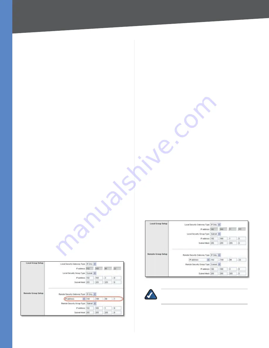
For the Remote Security Gateway Type, select
8.
IP Only
.
Enter
192.168.99.1
in the
IP Address
field.
Router B’s IPSec VPN Settings
For the Remote Security Group Type, select
9.
Subnet
.
Enter Router A’s local network settings in the
IP Address
and
Subnet Mask
fields.
In the IPSec Setup section, select the appropriate
10.
encryption, authentication, and other key management
settings.
In the
11.
Preshared Key
field, enter a string for this key, for
example, 13572468.
If you need more detailed settings, click
12.
Advanced
Settings
. Otherwise, click
Save Settings
and proceed
to the next section, “Configuration of Router A.”
Configuration of Router A
Follow these instructions for Router A.
Launch the web browser for a networked computer,
1.
designated PC 1.
Access the web-based utility of Router A. (Refer to the
2.
User Guide of the RVL200 for details.)
Click the
3.
IPSec VPN
tab.
Click the
4.
Gateway to Gateway
tab.
Enter a name in the
5.
Tunnel Name
field.
For the VPN Tunnel setting, select
6.
Enable
.
For the Local Security Gateway Type, select
7.
IP Only
.
The WAN IP address of Router A will be automatically
detected.
For the Local Security Group Type, select
Subnet
. Enter
Router A’s local network settings in the
IP Address
and
Subnet Mask
fields.
Router A’s IPSec VPN Settings
NOTE:
This configuration is the same as the
configuration of Router A in scenario 1.
For the Remote Security Gateway Type, select
8.
IP Only
.
Enter Router B’s WAN IP address in the
IP Address
field.


