3-9
Cisco ONS 15200 Installation, Setup, and Test Manual
78-13765-01
Chapter 3 Installation
Caution
During the ONS 15252 MCU installation, two people are required to lift and hold the unit in position.
Step 1
Align the indented edge of one of the extension brackets with the equipment rack.
Step 2
Attach the indented edge of the extension bracket to the equipment rack with the mounting screws (UNC
12-24) provided with the panel adapter.
Step 3
Repeat Steps
and
for the second extension bracket.
Step 4
Once the extension brackets are secure, lift and align the MCU with the mounting holes.
Step 5
Attach the MCU to the extension brackets with eight screws (M6 or UNC 12-24).
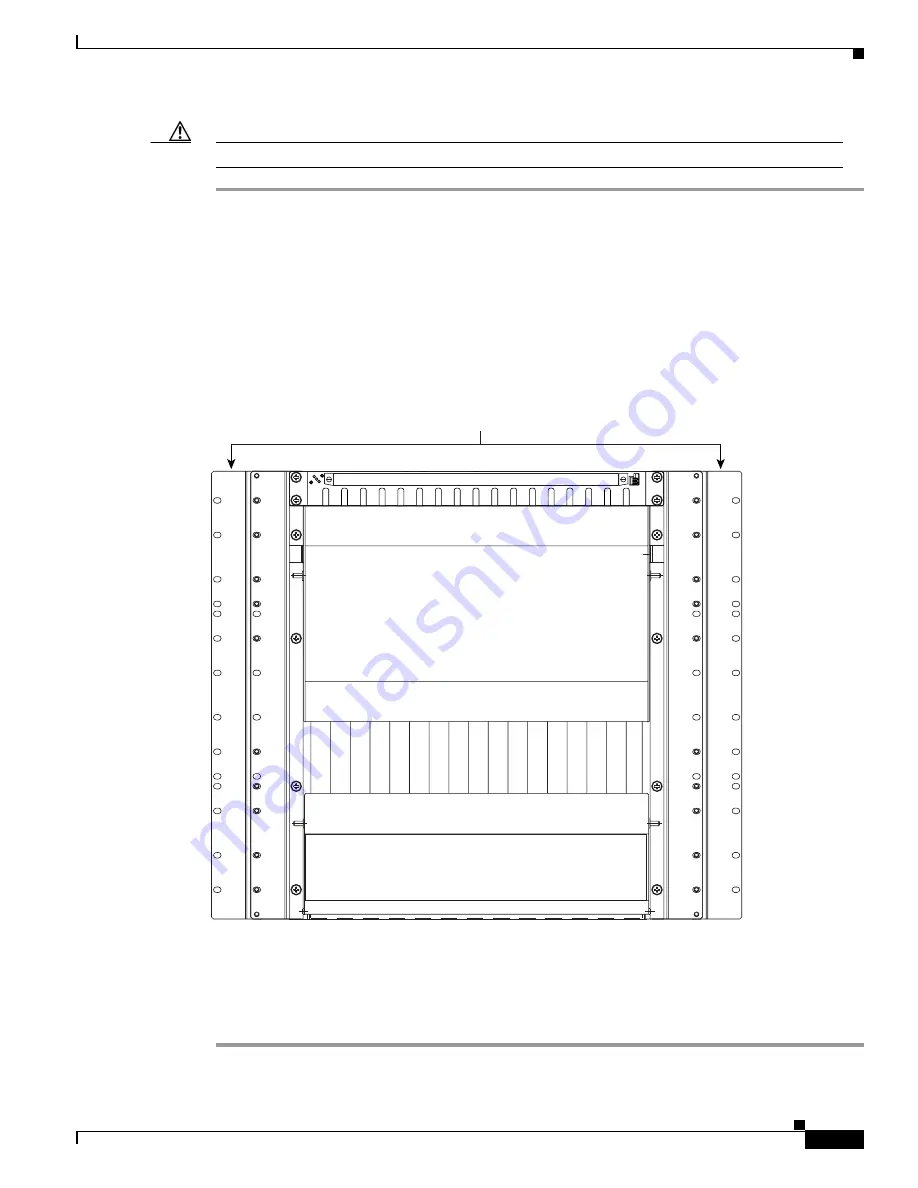
shows the extension brackets attached to the equipment rack.
Figure 3-5
Attached extension brackets
Step 6
Mount the cable ties (item 51-2587-01 in the accessory kit) to the racks. You will use the cable ties to
manage the cable in the
“Install the ONS 15252 MCU Fiber Cable” procedure on page 3-18
Procedure: Remove the ONS 15252 MCU Transport Crossbeam from the Passive Optical Shelf Door
Step 1
Open the passive optical shelf door.
67664
Extension brackets


