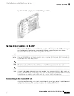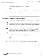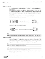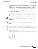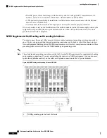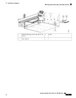
• Cisco NCS 4016 power trays (NCS4K-AC-PEM or NCS4K-DC-PEM)
• Cisco NCS 4009 power trays (NCS4K-AC-PEM or NCS4K-DC-PEM)
Steps
Follow these steps to install an AC or DC power tray into the chassis:
Procedure
Step 1
Slide the power tray into the bay until it engages its mating connector on the chassis.
Step 2
Fully seat the power tray into its mating connector and seat the power tray mounting ears against the chassis
mounting ears.
Step 3
Install and tighten the two screws, for each power tray, to a torque of 13.6 in-lb (1.5 N-m) through the power
tray mounting ears on each side into the screw holes in the chassis mounting ears to secure the tray to the
chassis.
Installing Power Modules
The following procedures describe how to install power modules into the chassis. The installation procedure
is the same for both AC or DC modules.
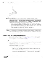
Never force a power module into the power tray if you feel any resistance! The power modules are keyed to
prevent AC modules from being plugged into a DC power tray or a DC module into an AC power tray. Forcing
a module into the incorrect tray can cause damage to the module and the tray.
Caution
Each power module has three status LEDs located on the front left side of its faceplate.
Table 3: Power Module LED Status Indicator Lights
Meaning
Color
LED Name
• On: The input voltage is present and within regulation range.
• Blinking: The input voltage is present but out of regulation range.
• Off: The input voltage is not present.
Green
Input OK
• On: The output voltage is on.
• Blinking: The power module is in a power limit or over current
condition.
• Off: The output voltage is off.
Green
Output
OK
• On: An internal fault is detected within the power module.
• Off: No internal faults detected on the power module.
Red
Fault
Installing AC or DC Power Modules
The following section describes how to install AC or DC power modules.
Hardware Installation Guide for the Cisco NCS 4000 Series
63
Installing Power Components
Installing Power Modules
Summary of Contents for NCS 4000 Series
Page 2: ......

