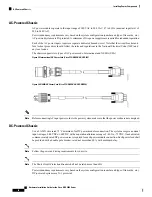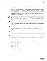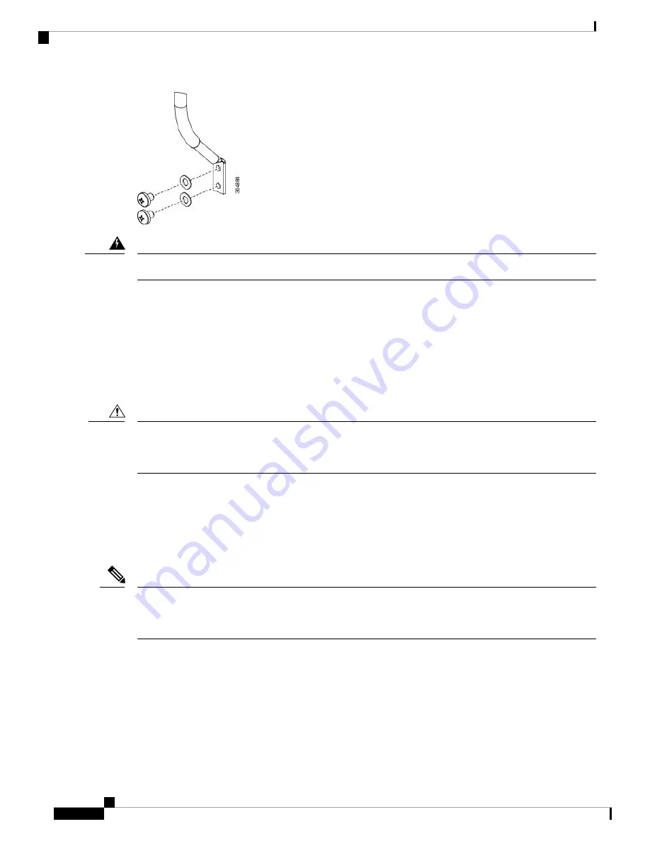
To avoid shock hazard, be sure to apply shrink wrap tubing around the wire entry area of the lug.
Warning
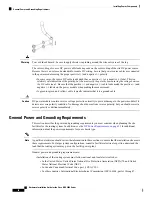
The color coding of source DC power cable leads depends on the color coding of the site DC power source.
Because there is no color code standard for source DC wiring, be sure that power source cables are connected
to the power modules using the proper positive (+) and negative (–) polarity:
• In some cases, the source DC cable leads might have a positive (+) or a negative (–) label. This is a
relatively safe indication of the polarity,
but you must verify the polarity by measuring the voltage between
the DC cable leads
. Be sure that the positive (+) and negative (–) cable leads match the positive (+) and
negative (–) labels on the power module when making the measurement.
• A green (or green and yellow) cable typically indicates that it is a ground cable.
DC power modules contain reverse voltage protection circuitry to prevent damage to the power module if it
detects a reverse polarity condition. No damage should occur from reverse polarity, but you should correct a
reverse polarity condition immediately.
Caution
General Power and Grounding Requirements
This section describes the power and grounding requirements you must consider when planning the site
facilities for the routing system. In addition, see the
DC Power Requirements, on page 55
for additional
information about the power requirements for your chassis type.
A qualified electrician should review the information in these sections to ensure that the installation site meets
these requirements. For larger system configurations, consult a facilities electrical expert to understand the
load that the routing system may put on the facility power plant.
Note
General power and grounding requirements are:
• Installation of the routing system must follow national and local electrical codes:
• In the United States: United States National Fire Protection Association (NFPA) 70 and United
States National Electrical Code (NEC).
• In Canada: Canadian Electrical Code, part I, CSA C22.1.
• In other countries: International Electrotechnical Commission (IEC) 60364, parts 1 through 7.
Hardware Installation Guide for the Cisco NCS 4000 Series
54
Installing Power Components
General Power and Grounding Requirements
Summary of Contents for NCS 4000 Series
Page 2: ......

