3-5
Cisco IR829 Integrated Services Router Hardware Installation Guide
Chapter 3 Connecting the Router
Connecting to DC Power
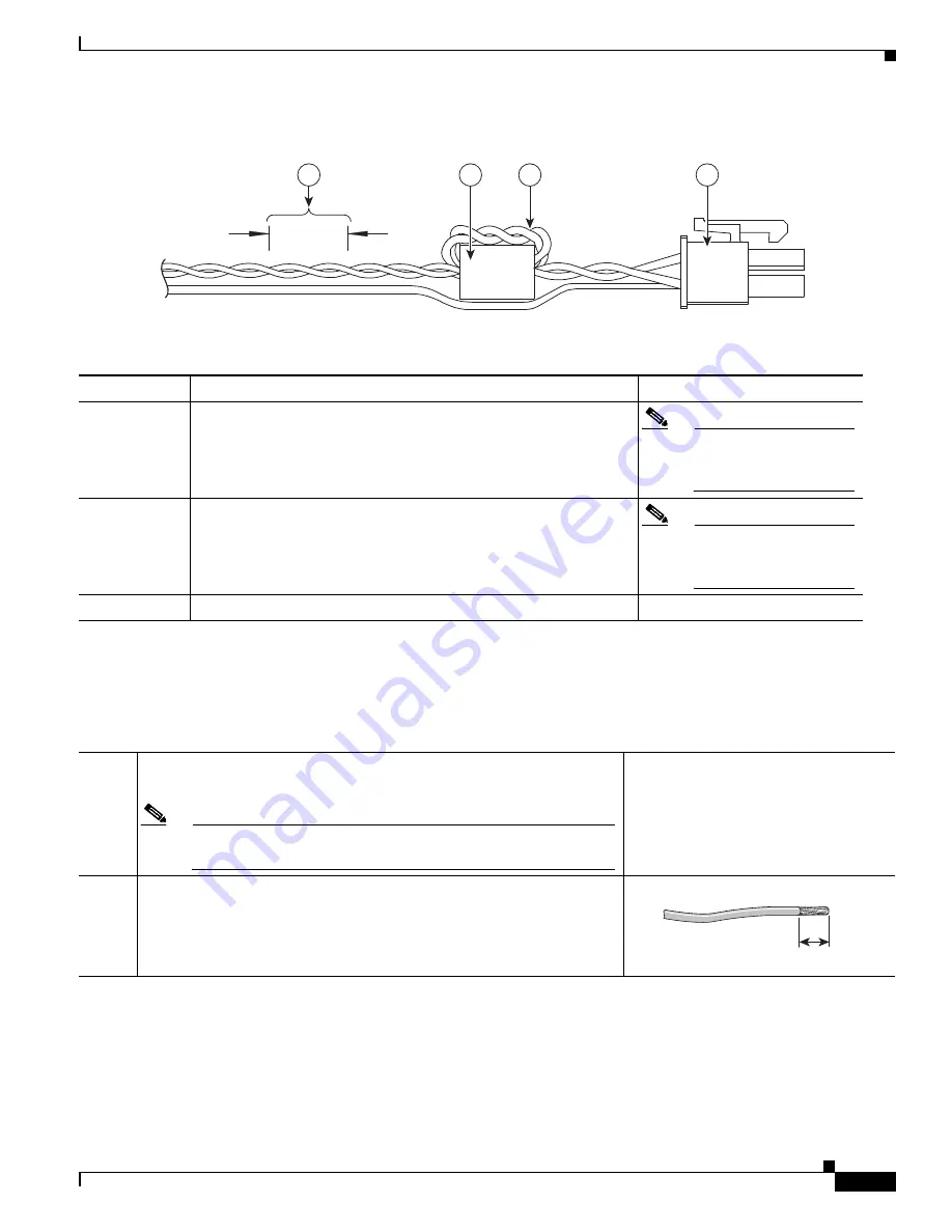
Figure 3-5
Power cable
Details listed in the power cable example are:
Wiring the DC Power
To connect the DC power on your Cisco IR829, follow these steps:
4
3
2
1
349790
1
4-pin locking connector
2
2 loops of DC power and power return wires only. Other wires that
may be used should run outside the Ferrite.
Note
Ferrite bead and the
loops of wire are not
needed at this time.
3
Ferrite Bead
Note
Ferrite bead and the
loops of wire are not
needed at this time.
4
Wires wound at 1 twist per inch
Step 1
Identify the DC power source and measure 4 strands of copper wire 16
AWG (1.29mm) long enough to connect to the DC power source.
Note
The maximum length of the cable
before
twisting is 15 feet (4.6
meters).
Step 2
Using an 16-gauge wire-stripping tool, strip each of the wires coming
from each DC-input power source to 0.25 inch (6.3 mm) ± 0.02 inch (0.5
mm). Do not strip more than 0.27 inch (6.8 mm) of insulation from the
wire. Stripping more than the recommended amount of wire can leave
exposed wire from the power connector after installation.
333084


