f)
Slide the gasket and seal the ring down the cable, thread the ring on to the body. Use caution to be sure
the gasket is correctly seated into the ring. Hand tighten to seal gasket fully.
g) Thread the seal nut on to the seal ring. Hand tighten until the ring grommet seals onto the cable jacket.
Step 6
Install the DC plug into the AP connector.
Connecting Data Cables
All the models of this AP support data connections through the Ethernet port and the Small Form-factor
Pluggable (SFP) port. However, both the Ethernet port and the SFP port cannot be used for data simultaneously.
If the SFP is detected and active, the Ethernet port is disconnected. If the SFP is not detected, the Ethernet
port stays connected.
If you are using the SFP port to deliver data through a fiber-optic cable, the AP must be powered by DC
power, power adapter, or a power injector.
For details on installing Ethernet cable, see
Installing a CAT 5e Ethernet Cable and Gland Assembly to the Access Point, on page 72
Installing a CAT 6/6A Ethernet Cable and Gland Assembly to the Access Point, on page 74
For details on installing a fiber-optic cable, see
Connecting a Fiber-optic Cable to the AP (AIR-SFP-KIT1=),
.
Connecting an Ethernet Cable to the Access Point
Installing a CAT 5e Ethernet Cable and Gland Assembly to the Access Point
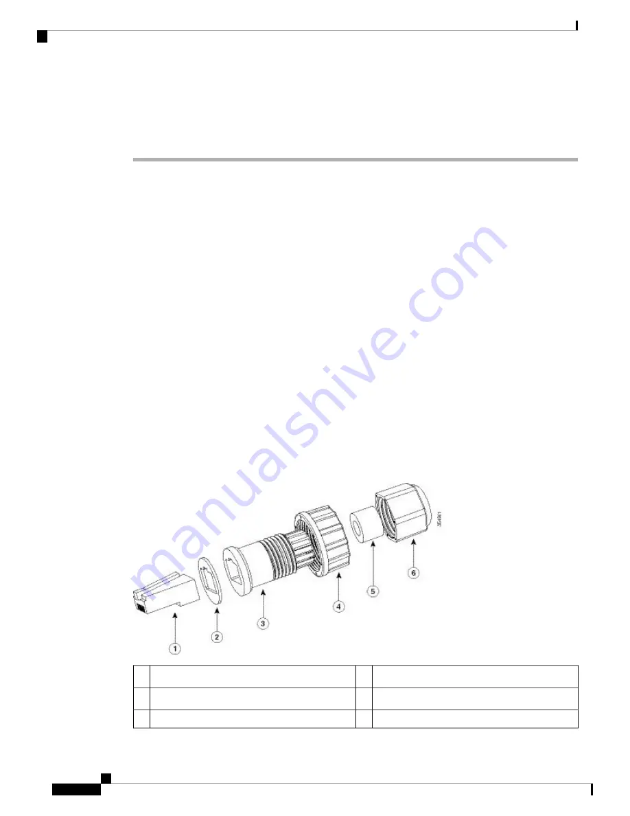
Figure 80: CAT 5e Cable Gland Assembly
Screw nut
4
CAT 5e RJ45 Plug
1
Seal
5
Gasket
2
Thread-lock sealing nut
6
Clamp ring
3
Cisco Catalyst 9124AX Series Outdoor Access Point Hardware Installation Guide
72
Installation Overview
Connecting Data Cables


