3
Cisco 820 Series and SOHO Series Routers Cabling and Setup Quick Start Guide
78-13937-04
1: Connect the Router to a PC
1: Connect the Router to a PC
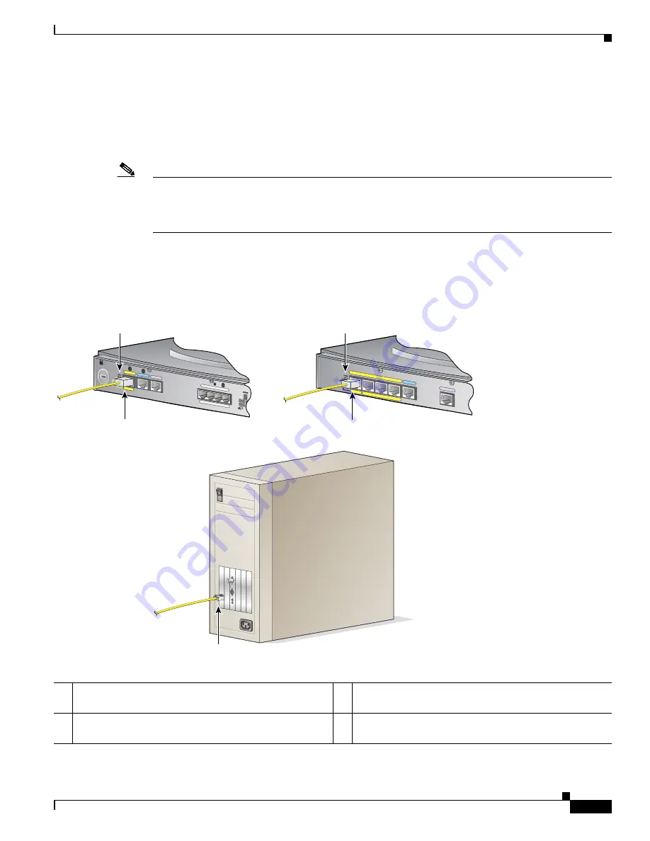
Follow the steps shown in
Figure 1 on page 3
to connect the router to a PC with an Ethernet network
interface card (NIC) installed.
Figure 1
shows portions of two router back panels. Refer to the back panel
that is similar to the back panel of the router that you are installing.
Note
Verify that the TO HUB/TO PC switch on the left side of the back panel has been set to the TO PC
position (out). If the button is in, press it to set it to the out position. You will know that the position is
correct if the LED for this port on the front of the router comes on after you have finished installing the
router and the PCs have been turned on.
To connect additional computers to Cisco 827H, Cisco 828, or SOHO 78 routers, obtain standard
Ethernet cables, and attach them to the router via Ethernet ports 1, 2, and 3.
Figure 1
Connecting the Router to a PC
1
Set TO HUB/TO PC button for Cisco 827, 827-4V, or
SOHO 77 router.
3
Connect yellow cable to Ethernet port on router.
2
Set TO HUB/TO PC button for Cisco 827H, 828,
SOHO 77H or SOHO 78 router.
4
Connect other end of cable to server, PC, or workstation.
ETHERNET 10B
ASE T
TO HUB
TO PC
4
3
2
1
Model Cisco 828
G.SHDSL
CONSOLE
ETHERNET
TO HUB
TO PC
+5,+12,-12,-24,-71 VDC
1
CONSOLE
Model Cisco 827-4V
ADSL
PHONE
2
1
4
3
74083
PC
2. Connect yellow cable to
ETHERNET port on router.
1. Set TO HUB/TO PC
button.
1. Set TO HUB/TO PC
button.
2. Connect yellow cable to
ETHERNET port on router.
Cisco 827, Cisco 827-4V,
or SOHO 77 router
Cisco 827H, Cisco 828,
SOHO 77H, or
SOHO 78 router
3. Connect other end of cable
to server, PC, or workstation.


