Connecting
Interface
Cables
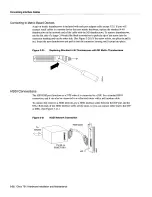
Figure
3-11
Single
Attachment
Station Single-Mode
Fiber
Network
Connections
To
primary
ring
From
primary
ring
FC
connectors
Single-mode
single
attachment
Use
two single-mode
cables
for
single
attachment
connection
Co
Figure
3-12
Single
Attachment
Station Multimode
Fiber
Network
Connections
To/from
primary
ring
Dual Attachment
Connections
MIC
Multimode
single
attachment
Use
one
multimode
cable
for
single
attachment
connection
CD
FIP
that
is
connected
as
DAS
connects
to
both
the primary
and
secondary
rings
The
signal
for
each
ring
is
received
on one
physical
interface
PHY
or
PHY
and
transmitted
from
the other
The
standard
connection
scheme
which
is
shown
in
Figure
3-13
for
DAS
dictates
that
the
primary
ring signal
comes
into the
FIP on
the
PHY
receive
port
and
returns
to
the primary
ring
from
the
PHY
transmit
port
The
secondary
ring
signal
comes
into
the
HP
on
the
PHY
receive
port
and
returns
to
the
secondary
ring
from
the
PHY
transmit
port
Failure
to
observe
this
relationship
will
prevent
the
FDDI
interface
from
initializing
Figure
3-16
shows
the connections
for
dual
attachment
that
uses
both
multimode and
single-mode
fiber
Figure
3-13
FDDI
DAS
Ports
Secondary
Primary
TX
RX
PHY
PHY
FORMAC
Secondary
Primary
CCC
CC
CC
3-16
Cisco
7513
Hardware
Installation
and
Maintenance
Summary of Contents for 7513 Series
Page 1: ......
Page 11: ...Cisco 7513 Hardware Installation and Maintenance ...
Page 121: ...Site Log 2 56 Cisco 7513 Hardware Installation and Maintenance ...
Page 162: ...Troubleshooting the Processor Subsystem 4 10 Cisco 7513 Hardware Installation and Maintenance ...
Page 266: ...Interface Processor LEDs B 16 Cisco 7513 Hardware Installation and Maintenance ...
Page 270: ...C 4 Cisco 7513 Hardware Installation and Maintenance ...
Page 288: ...18 Cisco 7513 Hardware Installation and Maintenance ...


