3-7
Catalyst 4500 E-Series Switches Installation Guide
OL-13972-02
Chapter 3 Installing the Switch
Establishing the System Ground Connection
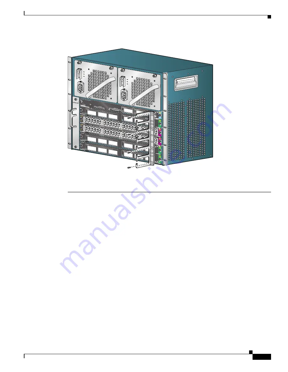
Figure 3-2
Attaching the Cable Guide to the Chassis (Catalyst 4506-E Switch Shown)
Step 6
Verify that on all installed supervisor engines and switching modules, the ejector levers are completely
closed and that the captive installation screws are tight.
Establishing the System Ground Connection
The system (NEBS) ground provides additional grounding for EMI shielding requirements and
grounding for the low voltage supplies (DC-DC converters) on the modules and is intended to satisfy the
Telcordia Technologies NEBS requirements for supplemental bonding and grounding connections.
Proper grounding practices ensure that the buildings and the installed equipment within them have
low-impedance connections and low-voltage differentials between chassis. When you include
NEBS-compliant system grounds, you reduce or prevent shock hazards, greatly reduce the chances of
equipment damage due to transients, and substantially reduce the potential for data corruption.
Without proper and complete system grounding, you run the risk of increased component damage due to
ESD. Additionally, you have a greatly increased chance of data corruption, system lockup, and frequent
system reboot situations by not using a system (NEBS compliant) ground.
231369
4506


