VCC-GC21U11PCL
Rev.
900-763-30-00
8.
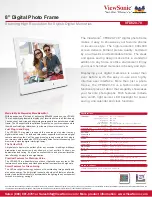
Partial Scan Mode
□
Maximum 8 partial areas can be set by serial commands.
Example
:
3 partial areas to be set.
Partial Scan Setting
©2013 CIS Corporation. All rights reserved.
19
①
:
V Blanking Line Number
②
:
Partial Area 1
③
:
Partial Area 2
④
:
Partial Area 3
⑤
:
Total Frame Line Number
FVAL
LVAL
①
⑤
②
③
④
Video Out
Partial scan start position 1
(
Address 064 & 065)
④
Partial scan start position 3
(
Address 068 & 069)
③
Partial scan effective lines 2
(Address 082&083)
Partial scan start position 2
(
Address 066 & 067)
②
Partial scan effective lines 3
(Address 084&085)
0
2047
Partial scan effective lines 1
(Address 080&081)
④
②
Partial scan effective lines 1
(Address 080&081)
Data sequence of output video
③
Partial scan effective lines 2
(Address 082&083)
Partial scan effective lines 3
(Address 084&085)