


VCC-12CL1M
Rev. 900-795-35-00
©2016 CIS Corporation. All rights reserved.
12
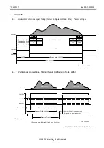
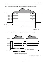
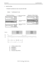
Med
iu
m
/Full
/1
0Ta
p
C
onf
igu
ra
tio
n
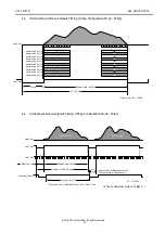
CL
Po
CL
Base
C
onf
igu
rat
io
n
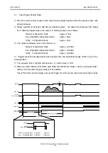
1
13
26
14
(SW1)
1
13
26
14
CL1
CL2
DC IN
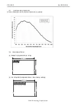
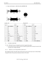
7.2.
Camera Link Connector
12226-1100-00PL (SUMITOMO 3M)
Connector (CL1)
Connector (CL2)
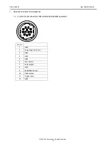
7.3.
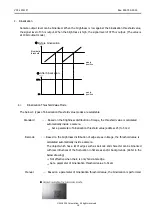
PoCL Selection Switch (SW1)
(1)
PoCL: Select when the power is supplied through the PoCL supported frame grabber.
If you set the switch to PoCL, make sure that the connected frame grabber board can supply the power from both
CL1 (Base) and CL2 (Medium/Full) sides.
(2)
CL:
Select when a non-PoCL supported frame grabber is used.
When changing the selection of the switch, please confirm that the power of the power supply source is turned OFF always.
Changing the switch at the powering up might cause malfunction to the camera.
Pin
No.
Pin
No.
Pin
No.
Pin
No.
1
NC/+12V(PoCL)
14
GND
1
NC/+12V(PoCL)
14
GND
2
X0-
15
X0+
2
Y0-
15
Y0+
3
X1-
16
X1+
3
Y1-
16
Y1+
4
X2-
17
X2+
4
Y2-
17
Y2+
5
Xclk-
18
Xclk+
5
Yclk-
18
Yclk+
6
X3-
19
X3+
6
Y3-
19
Y3+
7
SerTC+
20
SerTC-
7
100
Ω
20
Terminated
8
SerTFG-
21
8
Z0-
21
Z0+
9
CC1-
(Trigger IN -)
22
CC1+ (Trigger IN +)
9
Z1-
22
Z1+
10
100
Ω
23
Terminated
10 Z2-
23
Z2+
11
100
Ω
24
Terminated
11 Zclk-
24
Zclk+
12
100
Ω
25
Terminated
12 Z3-
25
Z3+
13
GND
26
NC/+12V(PoCL)
13
GND
26
NC/+12V(PoCL)
Summary of Contents for VCC-12CL1M
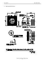
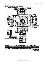
Page 25: ...VCC 12CL1M Rev 900 795 35 00 2016 CIS Corporation All rights reserved 25 15 Dimensions ...
Page 26: ...VCC 12CL1M Rev 900 795 35 00 2016 CIS Corporation All rights reserved 26 ...
Page 27: ...VCC 12CL1M Rev 900 795 35 00 2016 CIS Corporation All rights reserved 27 ...
Page 28: ...VCC 12CL1M Rev 900 795 35 00 2016 CIS Corporation All rights reserved 28 ...