background image


M7 – Owner’s Manual 

Page 

37


HRC Program Operation Procedure: 


THR Mode                                                    HRC Mode 

Press 

H.R.C   


button. 

Message window shows 

THR

” (

Target 

Heart Rate

), press 

▲ or ▼ button to select 

HRC 60

,

HRC 75

  or 

HRC 85

.


SET


“TARGET HEART 

RATE” 

then press ENTER 

button. 

SET


“BODYWEIGHT” 

then 

press ENTER button. 

SET


“TIME” 

then press 

ENTER button. 

SET


“AGE” 

then press 

ENTER button. 

SET


“BODYWEIGHT” 

then 

press ENTER button. 

SET


“TIME” 

then press 

ENTER button. 

Select 

HRC  60%

  or 

HRC 

75%

 or 

HRC 85%

 then press 

ENTER button. 

Press GO button to start 
workout. 

Press GO button to start 
workout.


SET


(Initial)


BEGIN SPEED” 

by 

press

 or 

button then press 

ENTER button. 
Heart Rate Control Formula: 

HRC 60%= (220-Age) x 60% 

HRC 75%= (220-Age) x 75% 

HRC 85%= (220-Age) x 85% 


SET


(Initial)


BEGIN INCLINE” 

by press

 or 

button then 

press ENTER button. 
 

Summary of Contents for M7

Page 1: ......

Page 2: ......

Page 3: ..._____26 3 2 Emergency Stop _______________________________________________________________________26 3 3 Quick Shift Optional __________________________________________________________________27 3 4 USB Port Fan Optional ______________________________________________________________27 3 5 Body Position _________________________________________________________________________27 4 CONSOLE OVERVIEW 2...

Page 4: ...ct has been designed and manufactured for studio use and even though we go to great efforts to ensure the quality of each product occasional errors and or omissions do occur In any event should you find this product to be defective in any way or to be missing parts please contact us No 12 6th Road Industrial Park Taichung Taiwan Tel 886 4 2359 1000 Fax 886 4 3505 5801 Email fitness pandfbrother co...

Page 5: ...This equipment contains moving parts Do NOT put fingers or other objects into the moving parts WARNING Before using this equipment to exercise always do stretching exercises first in order to properly warm up WARNING It s recommended to replace defective components immediately and keep the equipment out of use until repairs have been made by a professional person WARNING This equipment is designed...

Page 6: ...curely tightened before operating this equipment Periodic maintenance is required on all exercise equipment to keep it in good condition WARNING Incorrect excessive training can cause health injuries Stop using the equipment when feeling uncomfortable WARNING Turn OFF the power switch when the equipment is not in use WARNING If the power cord is damaged it must be replaced by the manufacturer or i...

Page 7: ...ovided with the treadmill If it doesn t fit the outlet get a proper outlet installed by a qualified technician 1 3 Electrical Requirements Important Voltage Information Before plugging the power cord into an electrical outlet verify that the voltage requirements for your area match the voltage of the treadmill that you have received The power requirements for the treadmill include a grounded dedic...

Page 8: ...efore your workout Fig 1 4 1 Fig 1 4 1 WARNING Always attach the Emergency Stop Key to your clothing during your workout When you use the machine only remove the Emergency Stop Key in an emergency WARNING When the key is removed while the machine is in operation it will stop quickly which could cause the loss of balance and possible injury Emergency Stop Button This unit is equipped with an Emerge...

Page 9: ...lay Type 6 LED 8 x 32 Dot Matrix Display Feedback Time Distance Heart Rate Calories Speed Incline Programs Target Rolling Valley Fat Burn Ramp Strength Interval Fitness Test 4 HRC USB Data Saving Charger Optional Fan Optional Quick Shift Standard Hand Pulse Standard Heart Rate Receiver Standard Chest Belt Optional Electrical Specifications Motor HP 3 0 HP Continuous 5 0 HP Treadmill Duty Motor Con...

Page 10: ...ncy Stop Button Key Adjustable Fan Optional Handlebar USB port Optional Motor Cover Quick Shift Optional Heart Rate Handlebar Footpad Cover Motor Cover Running Belt Bottle Holder Console Mast Console Set Power Switch Power Cord Inlet Transportation Wheel ...

Page 11: ... 2 3 1 Transportation WARNING Be sure the equipment is unplugged before moving To move the equipment carefully lift the rear end of the treadmill to allow the 2 front transportation wheels to make contact with the surface Fig 2 3 2 Carefully steer the equipment to another location Fig 2 3 2 IMPORTANT Be careful when moving this equipment as it is heavy and awkward If you do not feel comfortable mo...

Page 12: ...the Console Fig 2 4 1 Fig 2 4 1 3 Open the Carton 2 and remove the upper cardboard piece Fig 2 4 2 Fig 2 4 2 3 Remove all parts from the Carton 2 and card board inserts 4 Set the all the parts down near the spot where you plan to install the equipment 5 With the help of at least one other person remove all the packing materials and place the main body assembly on a level flat surface Carton 1 Cart...

Page 13: ...ist shown below NOTE Make sure that Serial Number on Carton 1 matches that on Carton 2 Carton 1 Carton 2 7 Hardware Kit Tools Refer to chapter 2 4 1 2 4 2 5 Right Left Console Handlebar Carton 1 1 Console Set 2 Right Left Console Mast 3 Packing 4 Right Left Console Mast Cover 6 Main Body Carton 2 ...

Page 14: ...6 PCS 2 M12 Lock Washers 6 PCS 3 M13 Flat Washers 6 PCS for Console Mast Set 1 M8 x 15mm Screws 8 PCS 2 M8 Lock Washers 8 PCS 3 Curve Washers 8 PCS for Console Mast Set Main Base STEP 5 STEP 6 M15 x15 mm Screws 4PCS for Console Mast Cover 1 M8 x 25mm Screws 4PCS 2 M8 Flat Washers 4 PCS 3 M8 Lock Washers 4 PCS for Console Handlebar ...

Page 15: ...M7 Owner s Manual Page14 2 4 2 Tools Please verify the tools list as shown below Allen Wrench 5mm Allen Wrench 10mm T handle Allen Wrench Power Cord Owner s Manual End Caps ...

Page 16: ...EP 1 Remove the Motor Cover Unscrew the 4 Motor Cover Screws 1 with the provided 5mm Allen Wrench Fig 2 5 1 Put the Motor Cover 2 aside Fig2 5 1 Fig 2 5 1 Required Tool Required Parts Hardware Kit Allen Wrench 5 mm N A Motor Cover 2 Motor Cover Screws 1 ...

Page 17: ...t Console Masts 3 4 on the front corner of the Main Body Fig2 5 2B 3 Tighten 6 M12x30mm Screws 5 and 6 S Washers 6 and 6 M13 Washers 7 with 10 mm Allen Wrench Fig2 5 2B NOTE Do NOT secure these screws tightly in this setp Fig 2 5 2B Required Tool Required Parts Hardware Kit Allen Wrench 10 mm Right Left Console Mast M12 x 30 mm Screws 6 PCS M12 Wave Washers 6 PCS M13 Flat Washers 6 PCS Right Conso...

Page 18: ... 1 and 2 Packings 2 into two sides of console mast Fig2 5 3 NOTE The Right Console Mast Cover is in a green bag and the Left Console Mast Cover is in a transparent bag Fig 2 5 3 Required Tool Required Parts Hardware Kit N A Packing 2 PCS Left Right Console Mast Covers Packings 2 Left Right Console Mast Covers 1 ...

Page 19: ...rs 3 and 8 Curve Washers 4 with a 5mm Allen Wrench Fig2 5 4A 3 Put 4 End Caps 5 into console lower cover Fig2 5 4B Fig 2 5 4A Fig 2 5 4B 4 Tighten 6 M12x30mm Screws on the lower console mast mentioned in STEP 2 Fig 2 5 4C Fig 2 5 4C Required Tool Required Parts Hardware Kit Allen Wrench 5 mm M8 x 15mm Screws 8 PCS M8 Lock Washers 8 PCS Curve Washers 8 PCS End Cap 5 End Cap 5 Console Cable 1 End Ca...

Page 20: ...einstall Motor Cover Reinstall the Motor Cover 1 by securing the 4 M15 x15 mm Screws 2 with a 5mm Allen Wrench Fig2 5 5 Fig 2 5 5 Required Tool Required Parts Hardware Kit Allen Wrench 5 mm M15 x15 mm Screws 4PCS Motor Cover 1 M15 x15 mm Screw 2 ...

Page 21: ...in a transparent bag Fig 2 5 6 Required Tool Required Parts Hardware Kit T handle Allen Wrench M8 x 25mm Screws 4PCS M8 Flat Washers 4 PCS M8 Wave Washers 4 PCS STEP 7 Connect the Power Plug the Power Cord 1 to the Power Cord Inlet 2 and plug the other end into an Electrical Outlet 3 Fig 2 5 7 Fig 2 5 7 Required Tool Required Parts Hardware Kit N A Power Cord Power Cord 1 Power Cord Inlet 2 Electr...

Page 22: ...justment Fig 2 6 1 Fig 2 6 1 Make balance adjustment directly from the Height Adjustment Bolts located in the supporting pads Fig 2 6 2 The unit should rest evenly on its supporting pads without vibration or swiveling Fig 2 6 2 Reinstall the Adjustable Pad Cover 1 after leveling is completed Fig 2 6 3 Adjustable Pad Cover 1 Screw 2 Screw 3 Height Adjustment Bolts ...

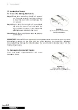
Page 23: ...enter the running belt manually The centering procedures are below Step1 Start the treadmill without anyone on the running belt press SPEED UP button until speed reached 6 KPH 3 7 MPH Step2 Observe whether the running belt is toward the right or left side of the deck a If toward the left side of the deck Using wrench turn the left adjustment bolt clockwise 1 4 turn and the right adjustment bolt co...

Page 24: ... the frame Step3 Repeat Step 1 and Step 2 until the slipping is eliminated IMPORTANT Be careful not to tighten the running belt tension too much as you can create excessively pressure on the front and rear roller bearings An excessively tightened running belt may damage the roller bearings that would result in bearing noise from the front and rear rollers To decrease the Running Belt Tension Turn ...

Page 25: ...ss ENTER button to return to IDEL mode Min Speed Setting Message Window shows SET MIN SPEED THEN PRESS ENTER SPEED window shows the current value press or button change to OFF press ENTER button to next setting Max Speed Setting Message Window shows SET MAX SPEED THEN PRESS ENTER SPEED window shows the current value press or button change to OFF press ENTER button to next setting Max Elevation Set...

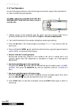
Page 26: ... the SPEED key until the treadmill reaches a speed of approximately 4 mph 6 4 KPH as indicated on the display 5 Observe if the belt is running properly Running belt should stay centered in the middle of the deck If running belt is not centered please make fine adjustment as descripted in chapter 2 6 2 Running Belt Adjustments 6 Run the treadmill through its full speed range First press the SPEED b...

Page 27: ...arately for a hands free workout Heart Rate Handlebar Standard Place the palms of your hands directly on the heart rate handlebars Both hands must grip the bars for your heart rate to register When gripping the handlebars do not grip tightly It is recommended that you hold the handlebars only long enough to see your heart rate readout on the console Fig 3 1 1 Chest Belt Optional Prior to wearing t...

Page 28: ...ger and it will not upload any file data from your Smartphone to the treadmill console Charging specification 5V 0 5A Fan Optional Fan on the console provides a cool breeze while exercising Press the Fan button to active multiple levels Fig 3 4 1 3 5 Body Position WARNING Walking or running backwards is prohibited Do NOT lean too far forward or back The correct position is with your head up should...

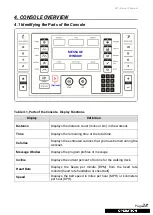
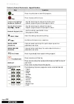
Page 29: ...ing time or the total time Calories Displays the estimated calories that you have burned during the workout Message Window Displays the program profiles or message Incline Displays the current percent of Incline for the walking deck Heart Rate Displays the beats per minute BPM from the heart rate monitor heart rate handlebar or chest belt Speed Displays the belt speed in miles per hour MPH or kilo...

Page 30: ...alues Rest Clear Clear the setting value while setting Enter Confirms information or a selection QUICK SPEED 4 6 8 10 4 preset speed quick keys for quick adjust speed to a predetermined value QUICK INCLINE 2 4 6 8 4 preset incline quick keys for quick adjust incline to a predetermined value Cool Down Press to gradually lower speed of the program Fan Optional Press to turn on off the fan DISPLAY Pr...

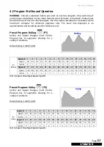
Page 31: ...2 3 4 5 6 7 8 9 10 11 12 13 14 15 16 Speed 50 50 60 60 70 80 90 100 90 80 70 60 60 70 80 90 Incline 0 1 2 3 4 5 6 6 5 4 3 2 1 2 3 4 Segment 17 18 19 20 21 22 23 24 25 26 27 28 29 30 31 32 Speed 100 100 90 80 80 70 70 60 60 70 80 90 90 80 70 50 Incline 5 6 5 4 3 2 1 1 2 3 4 5 6 5 4 2 Unit Speed Max Target Speed x Speed Preset Program Valley P2 Incline and Speed changes Each Profile Program has 32 s...

Page 32: ...100 100 100 100 100 100 100 90 80 70 60 50 Incline 3 3 4 5 4 4 3 2 2 3 5 4 3 2 1 0 Unit Speed Max Target Speed x Speed Preset Program Ramp P4 Incline and Speed changes Each Profile Program has 32 segments allowing for a variety of workouts Defalut Setting 4 MPH 6 KPH P4 Ramp Segment 1 2 3 4 5 6 7 8 9 10 11 12 13 14 15 16 Speed 50 50 50 50 50 60 60 60 60 60 70 70 70 70 70 80 Incline 0 1 2 1 3 2 3 4...

Page 33: ...80 70 70 70 60 60 60 50 50 50 Incline 4 3 6 5 4 3 3 6 5 7 7 5 3 1 0 0 Unit Speed Max Target Speed x Speed Preset Program Interval P6 Incline and Speed changes Each Profile Program has 32 segments allowing for a variety of workouts Defalut Setting 5 MPH 7 KPH P6 INTERVAL Segment 1 2 3 4 5 6 7 8 9 10 11 12 13 14 15 16 Speed 50 50 60 60 70 80 90 50 50 90 100 50 50 60 70 90 Incline 0 1 2 3 5 2 3 6 2 3...

Page 34: ...lly Set Bodyweight then press ENTER button Set Time then press ENTER button Change Profile by press or button Press GO button to start workout Press the preset program Random button Rolling Valley Fat Burn Ramp Strength Interval Random Press one of the preset program buttons Set Time then press ENTER button Message Window shows the program profile Set Max Speed by press or button Set Bodyweight th...

Page 35: ...If there are no pre set targets then the program will not end until the Stop button is pressed Set Bodyweight then press ENTER button Set Time then press ENTER button Set Distance then press ENTER button Set Calories then press ENTER button Press GO button to start workout Set Initial Begin Speed by press or button then press ENTER button Press Target button Set Initial Begin Incline by press or b...

Page 36: ... Male 3 0 KM 2 7 3 0 KM 2 5 2 69 KM 2 3 2 49 KM 2 3 KM Female 2 3 KM 2 1 2 3 KM 1 8 2 09 KM 1 7 1 79 KM 1 7 KM 21 29 Male 2 8 KM 2 4 2 8 KM 2 2 2 39 KM 1 6 2 19 KM 1 6 KM Female 2 7 KM 2 2 2 7 KM 1 8 2 19 KM 1 5 1 79 KM 1 5 KM 30 39 Male 2 7 KM 2 3 2 7 KM 1 9 2 29 KM 1 5 1 89 KM 1 5 KM Female 2 5 KM 2 0 2 5 KM 1 7 1 99 KM 1 4 1 69 KM 1 4 KM 40 49 Male 2 5 KM 2 1 2 5 KM 1 7 2 09 KM 1 4 1 69 KM 1 4 ...

Page 37: ... will adjust the incline level until the Actual Heart Rate reaches a point within 5 or 5 beats of the Preset Heart Rate If the Actual Heart Rate is less than or equal to the Preset Heart Rate 5 the incline level will be increased by 1 level every 30 seconds until it reaches the maximum level If the Actual Heart Rate is more than or equal to the Preset Heart Rate 5 the incline level will be decreas...

Page 38: ...TIME then press ENTER button SET AGE then press ENTER button SET BODYWEIGHT then press ENTER button SET TIME then press ENTER button Select HRC 60 or HRC 75 or HRC 85 then press ENTER button Press GO button to start workout Press GO button to start workout SET Initial BEGIN SPEED by press or button then press ENTER button Heart Rate Control Formula HRC 60 220 Age x 60 HRC 75 220 Age x 75 HRC 85 22...

Page 39: ...alue Press ENTER button to return to IDEL mode Min Speed Setting Message Window shows SET MIN SPEED THEN PRESS ENTER SPEED window shows the current value press or button change to OFF press ENTER button to next setting Max Speed Setting Message Window shows SET MAX SPEED THEN PRESS ENTER SPEED window shows the current value press or button change to OFF press ENTER button to next setting Max Eleva...

Page 40: ...st 009 8 019 Speed 6 029 H R C 010 9 020 Speed 8 030 Software Version Message Window shows VER time window shows software version press ENTER to start Test Mode LED ON OFF Test All the led displays will light up then light off Press ENTER button to next test LED Scan Mode This is for production test mode press ENTER button to next test Keys Test Message window shows KEY each key has their own code...

Page 41: ...ole Use a 100 cotton cloth lightly moistened with water and a mild liquid cleaning product to clean Other fabrics including paper towels may scratch the surface Do NOT use ammonia or acid based cleaners Brush away any wax deposits from the deck and belt area 6 2 Preventive Maintenance Schedule Follow the schedule below to ensure proper operation of this equipment Number Checking Item Daily Week Mo...

Page 42: ...t insert PINs C Check fuse near on off switch is worked or not if worked push it back and restart again if work please maintenance the running belt and deck D Turn off power then open the motor cover turn on the power and check the console power pilot lamp LED2 where on the interface PCB it shall be light completely if not replace it Display not completely illuminating A Console is damaged B Conso...

Page 43: ... application of inverter error Analysis and Solution The inverter should be replaced 5 Distance Time Err EEr EEPROM of inverter error Analysis and Solution The inverter should be replaced 6 Distance Time Err LE The voltage is too low when in IDLE or setting mode Analysis and Solution Check the input voltage The input AC power shall be 110V 220V system 65V 110V system or will show LE 7 Distance Tim...

Page 44: ...date the console program version to the newest version great than V1 06 15 Distance Time Err Err6 Incline motor cannot reach the preset set position within 42 seconds Analysis and Solution Does incline motor moving Incline motor jammed to eliminate jam problem then check the inverter shall be the new version refer to 1 3 and console firmware version great than V1 05 if not replace or update it Yes...

Page 45: ...Belt Adjustments in this Owner s Manual 6 6 Running Belt and Running Deck Service Schedule Running Belt and Running Deck are the consumables parts They should be replaced when the surface showing signs of wear We suggest the replacement of the running belt after 6000 hours usage or abnormal signs of wear ...

Page 46: ...7 Problem Description Example 1 The running belt is too dry and noisy Motor current is too high Example 2 Incline window showed Err All functions of the treadmill are normal except lift Our engineer has made diagnostics according to the document Engineering Manual Trouble Shooting Also there is a loud noise while pressing the UP button So he considers to be faulty Example 3 Display problem One led...

Page 47: ......

Page 48: ...M7 Owner s Manual Page46 ...

Reviews: