


09-2008
Plus 42 - 45 - 50 - 55
19
-
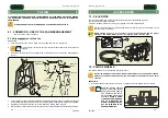
By positioning the lever in position “
c
”, drai-
ning of the tank is obtained.:
-
In order to carry out the complete discharge
of any liquid remaining in the pump and pipes,
set the tap (P15) to position “
d
”.
Remove the filler cap before shifting
the drain cock lever. When the
draining has taken place, return the
lever to the working position
(position “a”) and screw the cap
back on. These operations must be
carried out with the machine
stopped.
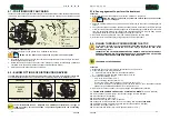
P4 - CENTRIFUGAL PUMP
00965
00300
P
d
b
a
c
P4
P7
Remove the filler cap before shifting the drain cock lever. When the draining has
taken place, return the lever to the working position (position “a”) and screw the
cap back on. These operations must be carried out with the machine stopped.
P16 - DISCHARGE CONNECTION WITH PLUG
(Versions with rinsing tank)
Connected to the spray-line rinsing tank trough suction piping (T7) and fixed to rinsing tap (P15).
Fixed to the left-hand side of the machine, it is connected to the tank through the pipeline (T1), to the
three-way faucet (P6) and to the hydraulic agitation system for the mixture.
THE PUMP MUST NEVER RUN DRY
P6 - 3-WAY LEVER TAP
It is mounted on the centrifugal pump (P4) and is
connected to the body of the filter (P8).
When the tap’s lever is set in position:
a. WORK (Vertically, downwards)
The mixture is sent both to the filter (P7) and the
tank (P6) through the pipelines (T2) and (T9), for
the hydraulic agitation of the mixture. In this
position, by opening the distributor (P9) (or E9),
the mixture is sent to the sprayhead.
TREATMENTS MUST BE CARRIED OUT
ONLY WITH THE TAP IN THIS POSITION.
d
b
a
c
P15
P16
FILTER
Plus 42 - 45 - 50 - 55
09-2008
50
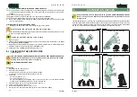
13.2 - FAN SHAFT SUPPORT OIL LEVEL CHECK
1.
Unscrew and remove the oil filling plug with the dipstick.
2.
Clean the dipstick and introduce it again.
3.
Extract the dipstick and check the oil level, which has to be between the two minimum and maximum
level notches of the dipstick itself.
Should it be necessary to top up the level, add some SAE 90 oil, up to reach the dipstick upper notch
(MAX).
4.
Introduce and screw the oil filling plug with the dipstick.
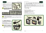
13.3 - FAN SHAFT SUPPORT OIL REPLACEMENT
Let the fan support oil replacement intervention be carried out at a C.I.M.A.
customers’ service centre, or observe the regulations in force for the disposal
of the used oil.
1.
Unscrew and remove the oil filling plug with the dipstick.
2.
Remove the oil drain plug and let the oil completely flow out from the fan shaft support.
3.
Check the oil drain plug and the relevant seal for integrity, replace them, if necessary, and close
again the oil drain plug.
4.
Through the filling pipe, pour a SAE 90 oil proper quantity, up to reach the MAX notch on the dipstick:
- about 0,19 kg for the PLUS 42 and 45 models
- about 0,24 kg for the PLUS 50 and 55 models.
5.
Position again the plug with the dipstick and close the oil filling pipe.
MAX
MIN.
BREATHER
PIPE
OIL DRAIN
PLUG
FAN SHAFT SUPPORT
OIL FILLING PLUG
WITH DIPSTICK
DIPSTICK
00307
OIL FILLING
PIPE
OIL FILLING PLUG


