SERVICE MANUAL
Transmig 165
ST
Transmig 165
ST
SERVICE MANUAL
Transmig 165
ST
Transmig 165
ST
TROUBLESHOOTING 10-16 Manual 0-5442
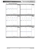
4
Wire Speed Calibration
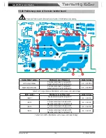
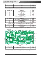
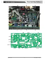
NOTE: these adjustments are on the wiring side of the main inverter module circuit board.
A
B
U02 pin 6
C
D
E U01 pin 1
F U01 pin 2
G U01 pin 3
0V for wiredrive circuit (R017)
W0 2 MIN SPEED
W05 MAX SPEED
A-09995
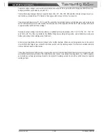
Select MIG mode on the front panel.
Remove the load from the output terminals.
Set front panel WIRESPEED (AMPS) potentiometer to minimum.
Adjust W02 trimpot until motor volts is 4.2V +/- 0.2V
Set front panel WIRESPEED (AMPS) potentiometer to maximum.
Adjust W05 trimpot until motor volts is 24.7V +/- 0.2V
Recheck settings
Set SW0-1 to OFF, SW0-1 to ON, SW0-3 to OFF, SW0-4 to ON to disable calibration of output volts & amps,
and calibration of wire feed speed and return to normal operation.
Summary of Contents for Transmig 165ST
Page 16: ...SERVICE MANUAL Transmig 165ST Transmig 165ST GENERAL INFORMATION 1 10 Manual 0 5442 Notes ...
Page 32: ...OPERATION 4 6 Manual 0 5442 SERVICE MANUAL Transmig 165ST Transmig 165ST Notes ...
Page 84: ...SERVICE MANUAL Transmig 165ST Transmig 165ST THEORY OF OPERATION 9 2 Manual 0 5442 Notes ...
Page 120: ...SERVICE MANUAL Transmig 165ST Transmig 165ST ASSEMBLY PROCEDURE 12 8 Manual 0 5442 Notes ...
Page 125: ...SERVICE MANUAL Transmig 165ST Transmig 165ST This Page Intentionally Blank ...


