SERVICE MANUAL
Transmig 165
ST
Transmig 165
ST
SERVICE MANUAL
Transmig 165
ST
Transmig 165
ST
TROUBLESHOOTING 10-4 Manual 0-5442
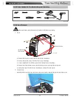
10.05 Clear Cover Sheet Removal
!
Read and follow safety information in Section 10.02 before proceeding.
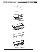
1. Clear protective sheet
Take out clear protective sheet.
1
Art # A-13006
10.06 Visually Inspect
Visually inspect the inside of the Power Source. The levels of current present in these units can cause burning
or arcing of PCB, transformers, switches, or rectifier when a failure occurs. Carefully inspect all components
within these units.
Look in particular for the following:
a) Loose or broken wires or connectors.
b) Burned or scorched parts or wires or evidence of arcing.
c) Any accumulation of metal dust or filings that may have caused shorting or arcing.
If any parts are damaged, they must be replaced. Refer to the Spare Parts section for a complete list of com-
ponents used in the Power Source.
Locate the faulty component(s) then replace where necessary.
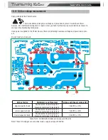
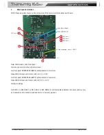
10.07 Preliminary DC Bus measurement of the main inverter board
!
Read and follow safety information in Section 10.02 before proceeding.
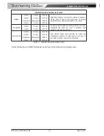
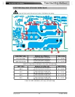
DC Bus Testing
Multimeter Lead Placement
Voltage with Supply voltage OFF
Upper capacitor bank
Positive meter lead to testpoint 1
Negative meter lead to testpoint 2
0 VDC
Lower capacitor bank
Positive meter lead to testpoint 3
Negative meter lead to testpoint 4
0 VDC
Table 10-3 DC BUS, Multimeter set to measure DC volts
Summary of Contents for Transmig 165ST
Page 16: ...SERVICE MANUAL Transmig 165ST Transmig 165ST GENERAL INFORMATION 1 10 Manual 0 5442 Notes ...
Page 32: ...OPERATION 4 6 Manual 0 5442 SERVICE MANUAL Transmig 165ST Transmig 165ST Notes ...
Page 84: ...SERVICE MANUAL Transmig 165ST Transmig 165ST THEORY OF OPERATION 9 2 Manual 0 5442 Notes ...
Page 120: ...SERVICE MANUAL Transmig 165ST Transmig 165ST ASSEMBLY PROCEDURE 12 8 Manual 0 5442 Notes ...
Page 125: ...SERVICE MANUAL Transmig 165ST Transmig 165ST This Page Intentionally Blank ...

