SERVICE MANUAL
Transmig 165
ST
Transmig 165
ST
SERVICE MANUAL
Transmig 165
ST
Transmig 165
ST
Manual 0-5442 5-3
MIG (GMAW) WELDING
Operation
With the regulator/flowmeter connected to cylinder or pipeline, and the adjustment screw/knob fully disengaged,
pressurize as follows:
1. Stand to one side of regulator/flowmeter and slowly open the cylinder valve. If opened quickly, a sudden
pressure surge may damage internal regulator/flowmeter parts.
2. With valves on downstream equipment closed, adjust regulator/flowmeter to approximate working
pressure. It is recommended that testing for leaks at the regulator/flowmeter connection points be
carried out using a suitable leak detection solution or soapy water.
3. Purge air or other unwanted welding grade shielding gas from equipment connected to the regulator/
flowmeter by individually opening then closing the equipment control valves. Complete purging may
take up to ten seconds or more, depending upon the length and size of the hose being purged.
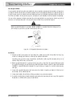
Adjusting Flow Rate
Art: A-05088_AB
Figure 5-2: Adjust Flow Rate
With the regulator/flowmeter ready for operation, adjust working flow rate as follows:
1. Slowly turn adjusting screw/knob in (clockwise) direction until the outlet gauge indicates the required
flow rate.
NOTE
It may be necessary to re-check the shielding gas regulator/flowmeter flow rate following the first
weld sequence due to back pressure present within shielding gas hose assembly.
2. To reduce flow rate, allow the welding grade shielding gas to discharge from regulator/flowmeter by
opening the downstream valve. Bleed welding grade shielding gas into a well ventilated area and away
from any ignition source. Turn adjusting screw counterclockwise, until the required flow rate is indicated
on the gauge. Close downstream valve.
Shutdown
Close cylinder valve whenever the regulator/flowmeter is not in use. To shut down for extended periods (more
than 30 minutes).
1. Close cylinder or upstream valve tightly.
2. Open downstream equipment valves to drain the lines. Bleed gas into a well ventilated area and away
from any ignition source.
3. After gas is drained completely, disengage adjusting screw and close downstream equipment valves.
4. Before transporting cylinders that are not secured on a cart designed for such purposes, remove
regulators/flowmeters.
Summary of Contents for Transmig 165ST
Page 16: ...SERVICE MANUAL Transmig 165ST Transmig 165ST GENERAL INFORMATION 1 10 Manual 0 5442 Notes ...
Page 32: ...OPERATION 4 6 Manual 0 5442 SERVICE MANUAL Transmig 165ST Transmig 165ST Notes ...
Page 84: ...SERVICE MANUAL Transmig 165ST Transmig 165ST THEORY OF OPERATION 9 2 Manual 0 5442 Notes ...
Page 120: ...SERVICE MANUAL Transmig 165ST Transmig 165ST ASSEMBLY PROCEDURE 12 8 Manual 0 5442 Notes ...
Page 125: ...SERVICE MANUAL Transmig 165ST Transmig 165ST This Page Intentionally Blank ...

