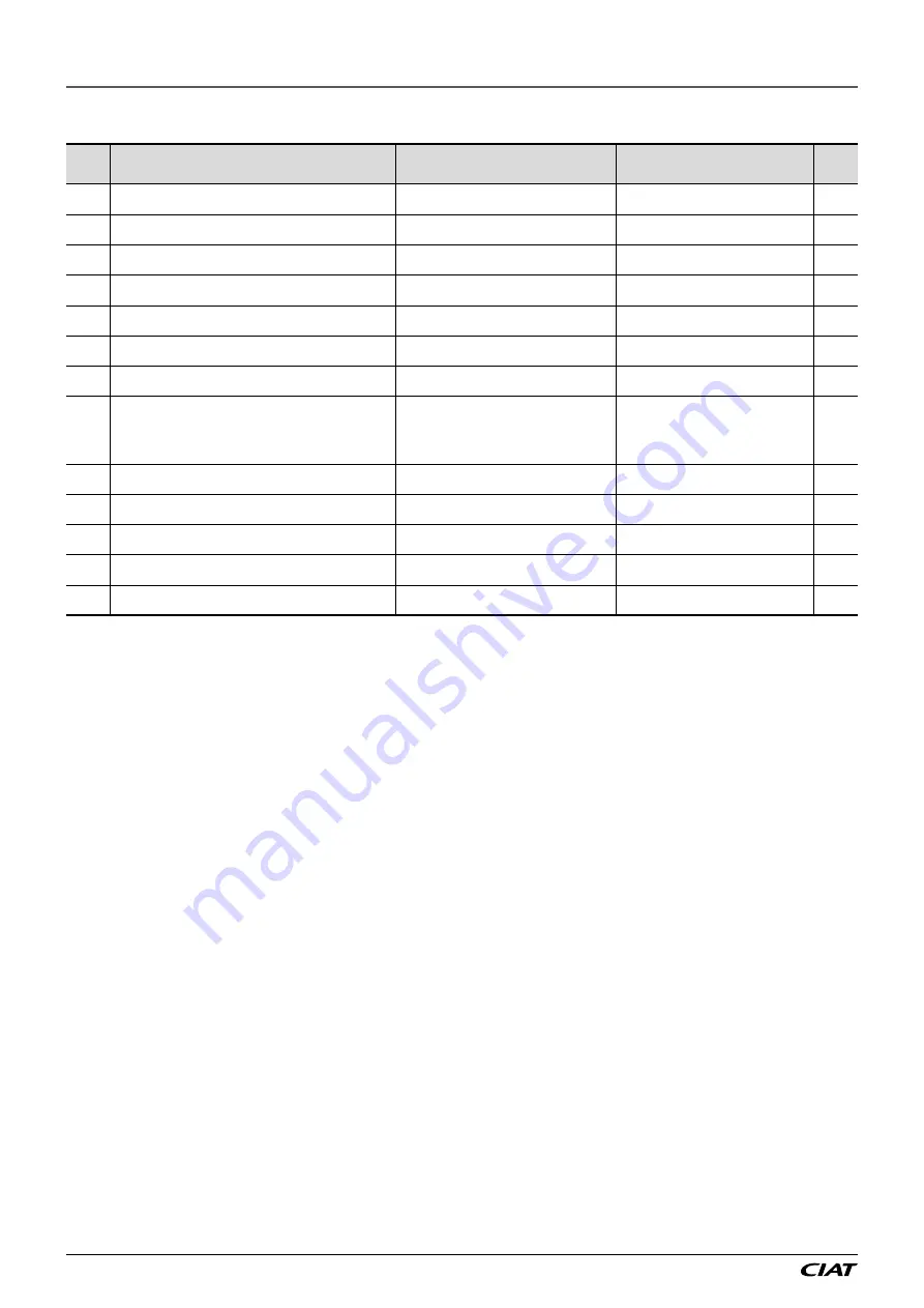
background image

8.8 - SW direction

No.

Description

Enumeration

Display conditions

Access 

level

850 Remote control input direction

0: Normally Open


1: Normally Closed

2

851 Setpoint 1/Setpoint 2 input direction

0: NO for setpoint 1


1: NC for setpoint 1

P160 setpoint 1/setpoint 2 selection = 


on/off input or on/off override

2

852 Fire detection input direction

0: Normally Open


1: Normally Closed

P24 Fire detection = With

3

855 Changeover thermostat input direction

0: Open in heating


1: Closed in cooling

P28 = mixed coil and P162 = On/Off input

3

860 Air intake fan check input direction

0: Normally Open


1: Normally Closed

3

861 Extraction fan check input direction

0: Normally Open


1: Normally Closed

3

863 Wheel heat recovery unit control input direction

0: Normally Open


1: Normally Closed

P36 Heat recovery unit = Gradual speed 

heat recovery unit

3

872 Electric heater manual safety input direction

0: Normally Open


1: Normally Closed

P32 Electric heater = 1 on/off stage


or 2 on/off stages 

or 1 gradual stage 

or 1 gradual stage and 1 on/off stage 

or P31 Electric preheater = with

3

878 Pump 1 check input direction

0: Normally Open


1: Normally Closed

P92 Coil 1 pump = With

3

879 Pump 2 check input direction

0: Normally Open


1: Normally Closed

P93 Coil 2 pump = With

3

880 Maintenance fault reporting output direction

0: Normally Open


1: Normally Closed

2

881 Danger fault reporting output direction

0: Normally Open


1: Normally Closed

2

885 AHU operating feedback output direction

0: Normally Open


1: Normally Closed

2

8 - PARAMETERS

FLOWAY 

EN-60 


Summary of Contents for FLOWAY CLASSIC PHE

Page 1: ...FLOWAY CLASSIC RHE PHE VERTICAL PHE 01 2021 EN7565703 02 C o n t r o l m a n u a l Compact AHU Control 2 V1 ...

Page 2: ...Y EN 2 The illustrations in this document are for illustrative purposes only and not part of any offer for sale or contract The manufacturer reserves the right to change the design at any time without notice ...

Page 3: ...E CONNECTION BETWEEN CONTROLLERS AND ALPHANUMERIC TERMINALS 29 4 1 One controller and one LCD terminal 29 4 2 Several controllers and terminals 29 4 3 Electrical connections for the pLAN local area network 30 4 4 Addressing the pLAN 31 5 CONNECTING TO A CMS 35 5 1 Modbus RTU 35 5 2 Modbus TCP IP and BACnet IP 36 5 3 LON 39 5 4 KNX 42 6 COMMISSIONING 45 6 1 Actions required prior to commissioning 4...

Page 4: ...ween several air handling units Simplified remote user control in the room to be conditioned This device is not designed to be used by persons including children with limited physical sensory or mental capabilities or by persons with insufficient experience or knowledge Only qualified personnel who have received in depth training in the equipment are authorised to work on the machine or modify the...

Page 5: ...a CMS so that it can be controlled remotely 2 2 Inputs outputs The PLC has analogue and on off inputs outputs The list of inputs outputs is described below depending on the options installed The controller is installed in the electrics box Input designation Type U Universal input analogue or on off GND C Shared DI Dry contact On Off input Y 0 10V analogue output Out Polarised 24 VAC On Off output ...

Page 6: ... 10V Hydraulic coil 1 valve control or electric heater triac control Y2 0 10V Hydraulic coil 2 valve control Y3 0 10V Intake fan control J7 DI1 Pump 1 fault DI2 Pump 2 fault DI3 Remote control DI4 Fire fault GND Shared J8 Not used J9 Vout Not used FBus1 Remote display connection in Th Tune room Tx Rx FBus1 Remote display connection in Th Tune room Tx Rx GND Remote display connection in Th Tune roo...

Page 7: ...c PHE Vertical PHE Supply air temperature sensor J2 U3 J2 U3 J2 U3 Return air temperature sensor J2 U2 J3 U4 J3 U4 Fresh air temperature sensor J3 U4 J2 U2 J2 U2 Intake fan pressure sensor J4 U7 J4 U7 J5 U9 Exhaust fan pressure sensor J5 U9 J5 U9 J4 U7 Intake filter fouling pressure sensor J4 U6 J5 U8 J5 U8 Exhaust filter fouling pressure sensor J5 U8 J4 U6 J4 U6 Customer terminals The following i...

Page 8: ...time schedule Icon Time schedule state No validated time schedule At least one time schedule is validated but not active At least one time schedule is validated and active U 01 Indicates the unit s address on the pLAN bus 15 30 Indicates the time 21 4 C Indicates the set temperature value room extraction or intake On Indicates the unit state Unit status Description Off The unit is off Off due to a...

Page 9: ...ated if operation requested and active Indicates a Cooling request Indicates a Heating request Indicates the operation of the fan s Indicates the Air quality operating mode 2 3 2 Menus The user interface is organised according to the menus below certain menus are only accessible when the access level is 2 or 3 see 3 18 and when the option is present on the machine 1 Machine status 2 Setpoints 3 Fa...

Page 10: ...to adjust the values of the monitoring parameters decrease This key has several functions 1 to manage the masks on the display previous mask 2 to go to the previous line in the menu 3 to adjust the values of the monitoring parameters increase Prg Switches the unit on Prg Switches the unit off Used to validate the data entered and go into a menu It is continuously backlit to indicate when the power...

Page 11: ...lation damper is in the process of opening Ventilation start up The ventilation is in the process of starting up Control active The control functions are active Control limited Certain control functions are not authorised E g flow rate insufficient for the electric heater operation Fan delay The AHU is in the process of shutting down but the ventilation remains active to cool the electric heaters ...

Page 12: ... 1 Weekly 4 1 Weekly 5 1 Weekly 6 1 Annual 1 1 Annual 2 1 Annual 3 1 Annual 4 1 Annual 5 1 Annual 6 1 Faults Current fault 1 Log 1 Faults level 2 Value reading Ventilation 1 Filters 1 Coils 1 Heat recovery units 1 Dampers 1 Pumps 1 Inputs Outputs 1 Temperatures 1 Counters 1 Setpoint change status 1 EC FMA Intake FMA 1 Exhaust FMA 1 Curves Temperature curves 1 Ventilation curves 1 Filter curves 1 2...

Page 13: ...elections Time delays 2 EC fans 3 Emulation PGD 3 Service Fault memory full 3 Machine parameters 3 Parameters back up 3 Operating readings 3 2 4 4 Use Action Start up shutdown From the home screen press and confirm Fault acknowledgement Press the alarm icon in the menu bar and press Status machine shut down red Status machine on green Status run request with the unit shut down flashing red green A...

Page 14: ...sent in the machine are visible Return or room air temperature Extraction flow Intake flow Fresh air temperature Supply air temperature Supply air duct pressure Pressing on each component will access the corresponding reading parameters A ring positioned beside each component indicates its status Grey inactive Green in operation Orange maintenance fault Red danger fault Access level Pressing on th...

Page 15: ...sure and filter differential pressure It is possible to choose the record duration 1 6 or 12 months the oldest values are erased which sets the sampling period 1 acquisition every 60 s for example 1 month 1 every 60 s 6 months 1 every 400 s 12 months 1 every 800 s Pressing brings up the curve settings zoom out on the vertical axis zoom out on the vertical axis zoom reset change horizontal axis dur...

Page 16: ...eter P160 is used to choose between setpoints 1 and 2 either by time schedule or via the J5 U10 on off input as well as by the CMS control or override via the J5 U10 on off input In the latter mode if the On Off input indicates setpoint 1 mode it is operating in setpoint 1 otherwise the operation is as per the last order received from the CMS or time schedule Parameter P161 is used to select wheth...

Page 17: ...erature control The set temperature may be The return air temperature The room temperature if the Th Tune room remote control is present The supply air temperature This choice is made via parameter P154 The temperature is set via a PID which calculates a heating requirement P395 or a cooling requirement P394 There is one heating setpoint P180 and one cooling setpoint P170 with the option to have a...

Page 18: ...ult P240 100 0 Supply air temperature Supply air upper limit setpoint P231 Proportional band P232 Integral time P233 High threshold fault P241 100 0 Heating request limitation 156 Supply air limitation With or Without 230 Supply air temperature low limit setpoint 231 Supply air temperature upper limit setpoint 232 Supply air temperature limit proportional band 233 Supply air temperature limit inte...

Page 19: ...ure upper limit threshold 242 Return air temperature low limit threshold 243 Return air temperature upper limit threshold 244 Room temperature low limit threshold 245 Room temperature upper limit threshold 3 7 Fan control The controller runs the plug fans with an EC motor The unit has one intake fan and one exhaust fan Pressure sensors for measuring the air flow rate are wired on the PLC The fans ...

Page 20: ...Exhaust duct pressure control PID derivative time D 142 Exhaust duct pressure lower limit threshold 143 Exhaust duct pressure upper limit threshold Faults The pressure sensors installed on the fans are also used to detect the presence of the air flow threshold P111 The PLC triggers a fault if the flow rate is greater or less than the fixed limits Flow rate control 110 AHU max flow rate 111 AHU flo...

Page 21: ...at recovery unit requirement Cooling 0 On Off None Off Off Heating 0 Off On Free cooling Night cooling Off Off 3 8 2 Heat recovery defrost Heat recovery unit frosting is monitored as standard via the fresh air temperature or optionally using a differential pressure sensor P37 37 Differential pressure sensor on the heat recovery unit With preheating coil There may be an electric heater to prevent f...

Page 22: ...lightly open settable value to maintain water circulation P260 This opening is maintained constantly including when the machine is shut down but still energised 248 Hydraulic coil frost protection safety threshold 260 Opening percentage for the coil 1 valve when unit stopped 261 Opening percentage for the coil 2 valve when unit stopped 3 9 3 Pumps It is possible to control pumps not supplied They ...

Page 23: ...is not monitored and the heat recovery unit and coil are shut down It is important to configure a fresh air temperature low limit which is sufficiently high to ensure no discomfort is caused 150 Free cooling control 206 Free cooling and night cooling operating differential compared to the controlled temperature 207 Temperature low limit for free cooling and night cooling 3 11 Night cooling The reg...

Page 24: ...the extraction fan is under duct pressure control In this scenario where the air intake fan is under duct pressure control the air quality sensor must be connected to terminal strip J26 U12 The control function only acts on the opening value of the mixing damper to allow a greater influx of fresh air 0 100 fresh air Mixing minimum opening percentage 1 2 IAQ requirement 100 152 Air quality control ...

Page 25: ...troller and at the end of the line between Th Tune terminals Tx and Tx see wiring diagram supplied with the machine Symbols Description mode Key has no effect Key has no effect This key is used to start or shut down the unit This knob has 2 functions Press used to alter the setpoint or parameter selected Rotation used to select a setpoint or parameter and modify it for more information see the tem...

Page 26: ...being set Mode selecting setpoint 1 or 2 this choice is visible only if the setpoint 1 2 selection is controlled by time slot or CMS P160 1 CsgC heating temperature setpoint 1 value CsgF cooling temperature setpoint 1 value Cali room temperature sensor calibration limited to 3 C 149 Th Tune 3 15 Temperature setpoint compensation The temperature setpoint compensation function is used to adjust the ...

Page 27: ... flow rate setpoint to be used for control purposes is the selected setpoint 1 or 2 multiplied by the downgrading percentage 271 Downgraded fresh air flow rate activation 271 1 Downgraded mode start fresh air temperature 271 2 Downgraded mode end fresh air temperature 271 3 min flow rate in downgraded mode 3 17 Time management The date and time are set using parameters P102 and P103 The date enabl...

Page 28: ...le of annual programming Annual programming between 15th October and 1st April the frost protection state will be active 3 19 Access level The PLC comprises 3 access levels which are used to prevent unauthorised persons from altering certain parameters Level 1 is the customer level It is freely accessible and is used to modify the setpoints Level 2 is the installer level It is protected by an acce...

Page 29: ... be performed on site Terminal address 32 Controller address 01 P01 Adr Priv Shared Trm1 32 Pr Trm2 None Sh Trm3 None OK 4 1 One controller and one LCD terminal The terminal addressing procedure is described in section 4 4 2 The procedure for the controller is in section 4 4 3 The controller and terminal must have different addresses The example above shows one addressing option 4 2 Several contro...

Page 30: ...cted in parallel using the J14 connector The first and last controller must be no more than 500 m apart 4 3 2 Connecting a remote screen to the pLAN The user can connect a user terminal to connector J15 up to a distance of 50m For a greater distance 2 TCONN boards and a AWG20 22 24 shielded cable comprising 2 twisted pairs and shielding must be used The shielded cable must be no longer than 200m 4...

Page 31: ...ust be equal to 16 Please ensure the addressing diagram below is respected J14 J15 J14 J15 J14 J15 P01 Adr Priv Shared Trm1 17 Pr Trm2 16 Sh Trm3 None OK Terminal address 17 Terminal address 18 Terminal address 16 Terminal address 19 P02 Adr Priv Shared Trm1 18 Pr Trm2 16 Sh Trm3 None OK P01 Adr Priv Shared Trm1 16 Sh Trm2 None Trm3 None OK No P03 Adr Priv Shared Trm1 19 Pr Trm2 16 Sh Trm3 None OK...

Page 32: ...minal s permanent memory Please note if you need to change the address of a controller using a terminal you may only do so with a terminal with the address 0 After having changed the controller address remember to change the terminal address from 0 to a different value to ensure normal operation 4 4 3 Modifying the controller addresses The value of the factory set address is 1 The controller pLAN ...

Page 33: ...the button again will bring up the mask sequences here on the right Here too the button will move the cursor from field to field The buttons will change the value of the current field The P xx field shows the address of the selected controller In the example shown No 12 is selected In the case of a shared display for a set of units maximum 31 the terminal must be configured on each unit in Sh mode...

Page 34: ...to 32 are displayed The small rectangles represent the terminals and the large rectangles the controllers If symbols appear then disappear the pLAN may be unstable or more likely two components share the same address The number after Term indicates the terminal address used The example shows that the network is made up of 3 controllers with the addresses 1 2 25 and 4 terminals with the addresses 3...

Page 35: ...n speed on the BMS2 port 0 1200 1 2400 2 4800 3 9600 4 19200 712 Parity on the BMS2 port 0 without 1 odd 2 even 713 Number of stop bits on the BMS2 port 715 Selection of the controller address on the BMS2 bus 149 Control type 0 Local 1 Remote ModBus The cable must be a type AWG20 22 24 Filotex FMA 2P Belden ref 9842 9842NH 24AWG or equivalent shielded cable not supplied comprising a twisted pair a...

Page 36: ... the reset button After approximately 8 seconds the left hand LED status LED changes from green to red and then starts flashing At this point release the button Powered up Release the button Button pressed Button Button Approx 8 s Button released Red Green The board is now initialised to the address 172 16 0 1 You will now need to configure your PC to a fixed IP Procedure for Windows 7 Important y...

Page 37: ...the mouse on the name of the network connection you wish to configure In the menu which appears select Properties Select the row Internet Protocol Version 4 TCP IPv4 Click the Properties button Enter the IP address 172 16 0 2 Subnet mask 255 255 0 0 Then confirm 5 CONNECTION TO A CMS EN 37 FLOWAY ...

Page 38: ...l now be connected to the web server For access the login is admin The password is fadmin Click in the Configuration menu and select the Network tab Complete this page with the information for your local network IP address Netmask Then in the pCO Com tab change the protocol to Modbus Extended and enter 200 digital variables 1550 analogue variables and 0 integer variables 5 CONNECTION TO A CMS FLOW...

Page 39: ...d If this is not the case switch off the controller and insert the board in J13 entitled BMS card or BMS1 on the controller It may be recharged on site using the nxe file available on request 1 Connector for the controller 2 Disconnectable terminal for connection of the LonWorks network GND A B 3 Service pin create a temporary shunt between the 2 terminals to create a service PIN disconnect this s...

Page 40: ...N network X Definition of the bindings between LON controllers and with the BMS X Definition of BMS setpoints and time schedules X X Method to be defined jointly by the integrator and installer Considering the central role of the integrator it is essential that the latter is included in the project as early as possible so as to be able to anticipate and validate the BMS architectures integration t...

Page 41: ...ollers to be created in the database as there are controllers present on the network The rest of the configuration creation of the bindings on the nvi nvo type datapoints is carried out normally as it would be for any other LON product Our PLC does not have any nci SCPT UCPT type datapoints The configuration parameters are only accessible from the HMI terminal 5 CONNECTION TO A CMS EN 41 FLOWAY ...

Page 42: ...tocol on the PLC adjust the following values in the Communication menu on the user terminal P700 Protocol KNX P716 Control type Local for KNX access to the read only datapoints Remote for KNX access to the read and write datapoints The manufacturer does not provide a system start up configuration parameter setting or KNX network addressing service The configuration of this type of network requires...

Page 43: ...ormat KNX range Boolean DPT_Switch 1 xxx 1 bit Off On Unsigned 8 bit DPT_Value_1_Ucount 5 xxx Unsigned 8 bits 0 to 255 Unsigned 16 bits DPT_Value_2_Ucount 7 xxx Unsigned 16 bits 0 to 65535 Floating 16 bits DPT_KNX_Float 9 xxx Floating 16 bits 671 088 64 to 670 760 96 32 bit signed DPT_Value_4_Count 13 xxx 32 bit signed 2 147 483 648 to 2 147 483 647 The air handling unit PLC comes as standard in t...

Page 44: ...The assignment of the individual address and the loading of the addresses and parameters are carried out as normal for any other KNX product 5 CONNECTION TO A CMS FLOWAY EN 44 ...

Page 45: ...SAFETY DEVICES ARE OPERATIONAL To access test mode you first need to set P99 no so as to shut down the unit Then go to the test menu and set P3500 override validated yes Choose the output to force by setting on for the on off outputs or by setting the desired percentage for the analogue outputs The last settings made in this menu remain in the memory after exiting test mode It is strongly recommen...

Page 46: ...st protection Danger 11 Intake EC motor Danger 31 Exhaust EC motor Danger 48 Intake air flow low limit Danger 49 Extraction air flow low limit Danger 52 Air intake filter 1 fouled Maintenance 53 Intake filter 1 blocked Danger 58 Exhaust filter 1 fouled Maintenance 59 Extraction filter 1 blocked Danger 62 Intake filter pressure sensor fault Danger 63 Exhaust filter pressure sensor fault Danger 65 R...

Page 47: ...covery unit is greater 345 Pa Operating problem with the differential pressure sensor Check the operation of the sensor The heat recovery unit is clogged Clean the heat recovery unit The heat recovery unit is frozen Wait for the heat recovery unit to be defrosted Electric heater safety thermostat One of the safety thermostats for an electric heater has been tripped The temperature in the electric ...

Page 48: ...e too high Operating problem with the heating elements Check the operation of the valves heat recovery unit mixing box etc Operating problem with the cooling elements Check the operation of the valves heat recovery unit mixing box etc Fresh air temperature sensor Temperature measurement 50 C or 90 C Temperature sensor open circuit or short circuit Check the sensor wiring or replace the sensor Supp...

Page 49: ...5 4 5V 2 3 11 Number of EC air exhaust fans 1 or 2 as per P1 Visible as read only 3 12 Characteristics of the pressure sensor for the air extraction fan 1 0 1000 Pa 10V 2 0 2500 Pa 10V 3 0 5000 Pa 10V 4 0 1600 Pa 0 3 5V 5 0 1000 Pa 0 5 4 5V 6 0 3000 Pa 0 5 4 5V as per P1 Visible as read only 3 13 Coefficient value K for the exhaust fan as per P1 Visible as read only 3 15 Exhaust filter type 1 M5 2...

Page 50: ...2 Duct pressure P104 Exhaust fan ventilation control Duct pressure and P37 Differential pressure sensor on heat recovery unit without 106 Multiplication factor value of the signal sent by the air extraction fan with pressure control in the supply air duct 1 P104 Intake ventilation control Duct pressure and P105 Exhaust fan control Control feedback or flow rate feedback 2 108 Damper opening time de...

Page 51: ... selection time sched CMS or on off input or on off override and P161 Application of setpoint 1 setpoint 2 selection ventilation or temperature ventilation 1 130 Air extraction fan flow rate control PID proportional band P 6000 m3 h P104 Air intake ventilation control Flow rate or P105 Air exhaust ventilation control Copy of the air intake fan flow rate 2 131 Air extraction fan flow rate control P...

Page 52: ...selection return or room air 2 157 Supply air compensation in deadband 0 without 1 with 1 P154 Target temperature selection return or room air 2 158 load shedding of rotary heat exchanger 0 free 1 forced stoped 0 P36 Heat recovery unit Gradual speed 2 160 Setpoint 1 Setpoint 2 selection 0 Without 1 Time sched or CMS 2 on off input only 3 On off input override 0 2 161 Application of setpoint 1 setp...

Page 53: ... setpoint in night cooling mode 200 Pa P151 Night cooling control With and P104 Intake ventilation control Pressure 2 215 Exhaust fan pressure setpoint in night cooling mode 200 Pa P151 Night cooling control With and P104 Intake ventilation control Pressure and P105 Exhaust ventilation control duct pressure 2 216 Air quality setpoint 800 ppm P152 Air quality control With 2 217 Air quality proporti...

Page 54: ...f 0 P28 Water coil no 1 Cooling or Heating 2 261 Opening percentage for the coil 2 valve when unit stopped 0 P29 Water coil no 2 Cooling or Heating or Mixed 2 265 Fresh air temperature limit for unit operation 12 C P36 Heat recovery unit Plate and P31 Electric preheater without 20 P36 Heat recovery unit Plate and P31 Electric preheater with 3 25 P36 Heat recovery unit Gradual speed 3 270 Temperatu...

Page 55: ...uled exhaust filter differential pressure calculated threshold 0 1000 1 Pa 1 317 Blocked exhaust filter differential pressure calculated threshold 0 1000 1 Pa 1 320 Calculated cooling setpoint 0 0 50 0 0 1 C 1 321 Calculated heating setpoint 0 0 50 0 0 1 C 1 322 Supply air temperature 99 0 99 9 0 1 C Last sensor in the direction of airflow 1 323 Fresh air temperature 99 0 99 9 0 1 C 1 324 Return a...

Page 56: ...ulated cooling demand 0 100 1 1 395 Calculated heating demand 0 100 1 1 398 Cooling block 0 no 1 yes 0 1 1 1 399 Heating block 0 no 1 yes 0 1 1 1 400 Coil 1 Cooling 0 100 1 P28 Coil no 1 mixed or cold water 1 401 Coil 1 Heating 0 100 1 P28 Coil no 1 mixed or hot water 1 404 Coil 2 Cooling 0 100 1 P29 Water coil no 2 cooling or mixed 1 405 Coil 2 Heating 0 100 1 P29 Water coil no 2 heating or mixed...

Page 57: ...f heat recovery unit Without 1 454 Heat recovery unit instantaneous efficiency 0 100 1 P38 Temperature sensor upstream of heat recovery unit With 1 456 Heat recovery unit bypass opening percentage 0 100 1 P36 Heat recovery unit Plate 1 470 Maintenance faults summary 0 off 1 on 0 1 1 1 471 Danger fault summary 0 off 1 on 0 1 1 1 490 Weekly programming request 0 inactive 1 active 0 1 1 1 491 State r...

Page 58: ...er 0 P146 Target temperature selection room 2 625 Room temperature too high 0 Maintenance 1 Danger 0 P146 Target temperature selection room 2 628 supply air duct pressure too low 0 Maintenance 1 Danger 0 P104 Air intake ventilation control Duct pressure 2 629 supply air duct pressure too high 0 Maintenance 1 Danger 0 P104 Air intake ventilation control Duct pressure 2 632 Loss of communication wit...

Page 59: ...ion No Description Setting Unit Display conditions Access level Min Max 800 Calibration of the air intake fan flow rate sensor 3 801 Calibration of the air extraction fan flow rate sensor 3 802 Intake duct pressure sensor calibration P104 Air intake ventilation control Duct pressure 3 803 Exhaust duct pressure sensor calibration P104 Intake ventilation control Duct pressure and P105 Exhaust ventil...

Page 60: ...en 1 Normally Closed 3 863 Wheel heat recovery unit control input direction 0 Normally Open 1 Normally Closed P36 Heat recovery unit Gradual speed heat recovery unit 3 872 Electric heater manual safety input direction 0 Normally Open 1 Normally Closed P32 Electric heater 1 on off stage or 2 on off stages or 1 gradual stage or 1 gradual stage and 1 on off stage or P31 Electric preheater with 3 878 ...

Page 61: ... Mixed 2 927 Hydraulic coil 2 operation end heating percentage P926 100 1 P29 Water coil no 2 Heating or Mixed 2 930 Electric heater operation start heating percentage 0 P931 1 P32 Electric heater 1 on off stage or 2 on off stages or 1 gradual stage or 1 gradual stage and 1 on off stage 2 931 Electric heater operation end heating percentage P930 100 1 P32 Electric heater 1 on off stage or 2 on off...

Page 62: ......

Page 63: ......

Page 64: ...Manufacturer CIAT SA Culoz France Printed in the European Union Manufacturer reserves the right to change any product specifications without notice ...

Reviews: