background image

      F004  

          F005                                                 

          0

1.0KHz

10.0KHz

Special Function

F082        AVR Function        Setting Range: 0~1        Factory Setting: 1

F082=0: Ineffective.

F082=1: Automatically stabilized the voltage.

Function Instruction: Such function is used to set the Inverter's voltage-stabilization 
     function.
Note: When F082=1 and input voltage > or = output voltage set value, AVR function will 
     ensure output voltage constant. When F082=1, input voltage < output voltage set 
     value, output voltage =input voltage

F083     Torque Hoisting     Setting Range: 0~30%     Factory Setting: 4%

Function Instruction: Such function is used to improve t he torq ue char acter w hen the 
     Inverter is operated in low frequency, through adjusting the output

 voltage of the 

     I nverter, it can improve the output moment in the operation in low frequency. If the 
     set value is to large, the Inverter will come out jump fault.
Note: When the torque hoisting is set to 0, the torque hoisting will be ineffective, the 
     Inverter will be operated according to the set val ue of V/F curve,  otherw ise V/F 
     curve set will be ineffective.

  Voltage

Frequency

F084   Slip Compensation   Setting Range: 0.0~5.0HZ   Factory Setting: 0.0HZ

Function Instruction: Such function is used to set the rated compensation frequency 
      value of the slip compensation. When load of motor increases, its rotational speed 
      will be down. The aim of slip compensation is to adjust output frequency to compen
      sate the reduced rotational speed, to make motor reach synchronizing speed more, 
      when the set value is 0.0, the slip compensation will not act.

F085  Carrier Wave Frequency    Setting Range: 1~12KHz    Factory Setting: 5

Function Instruction: The higher the carrier wave frequency is, the more perfect the 
     current waveform will be, the lower the motor noise will be, th e smaller the tor que 
     on low frequency will be, the larger electromagnetism disturbance will be, the larger 
     main element loss will be, the larger Inverter fever will be, the larger leakage 
     current will be, the lower the efficiency will be. The lower carrier wave frequency is, 
     it will be reverse.

Carrier Wave Frequency abridged general view is as below:

Carrier Wave 
Frequency

Electromagnetism 
Noise

Disturbance, 
Leakage Current

Fever Value

Large

Small

Small

Large

Small

Large

Note:  Carrier wave of Inverter above 30KW is factory set to 3.

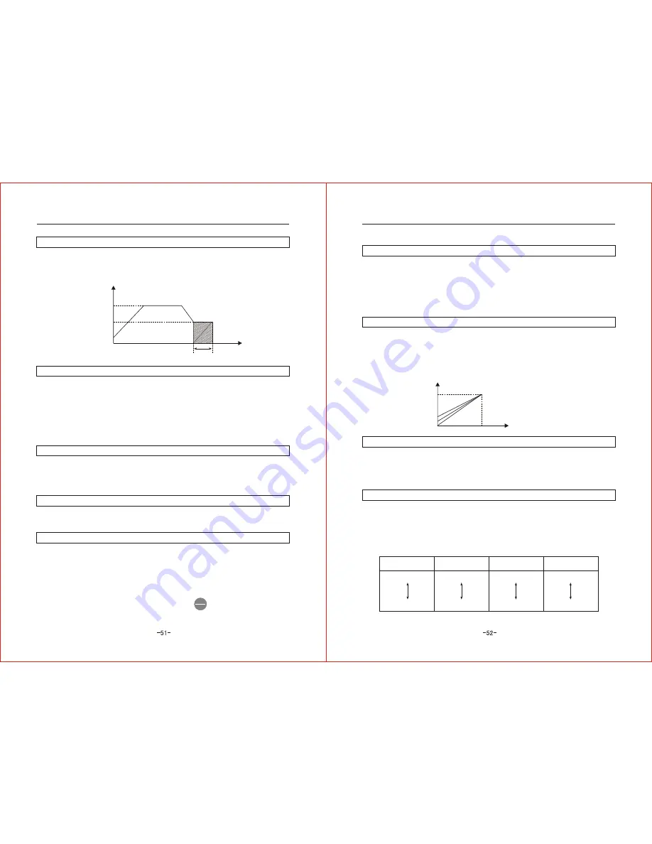
F077   DC Operation Torque    Setting Range: 0~30%     Factory Setting: 4%

Function Instruction: Such function is used to se

t the braking torque after in DC braking 

     to ensure to make the motor fully stop in braking time.
Note: If DC braking torque is set to high, the Inverter will easily stop. Increase it slowly 
     when setting the braking torque.

Output Frequency

        Operation Frequency

DC Braking Start Frequency

Time

DC Braking Time

Counter Function

F078     Count Mode      Setting Range: 0~2      Factory Setting: 0

F078=0: Count function is ineffective.
F078=1: Count function is effective, upward count mode.
F078=2: Count function is effective, downward count mode.

Function instruction: When choosing count function is effective (F078=1 or F078=2), 
     count pulse is input by multi-function (X1~X4), X1~X4 multi-function terminal must 
     have one of which to choose pulse input function (details are in function code F093
     ~F096 function choice), otherwise this function will be ineffective.

F079    Count Value       Setting Range: 0~9999    Factory Setting: 1

Function Ins truction: Such function is used to set the counter's default value, if choosing 
      upward count way, when count value is equal to the default value, it will stop count 
      and execute coun t to treatment action. If choosing downward count way, when count 
      value is 1, it will stop count and execute count to treatment action.

F080    Count Unit       Setting Range: 0~9999    Factory Setting: 1

Function Instruction: Such function is used to set the unit value of each count pulse and 
     could count relevant object.

F081    Count to Treatment       Setting Range: 0~3     Factory Setting: 0

F081=0: Stop count and close output.

F081=1: Stop count and continue output.

F081=2: Restart count and stop output.

F081=3: Restart count and continue output.

Function Ins truction: Such function is used to choose the action when the counter count 
      to time.
Note: Counter Zero Clearing Operation please press          . 

Article6    Function parameter illustration

Article6    Function parameter illustration

STOP
RESET

Summary of Contents for ZVFG7 series

Page 1: ...ZVFG7 SERIES ZVFP7 SERIES INVERTER USER S MANUAL INVERTER...

Page 2: ...ble shooting and etc of inverters Ensure that this manual is made available to the final user and keep it handy for future reference If there is any doubt or question please contact the Technical Serv...

Page 3: ...4 3 The content of dispay 27 Article 5 Run in test 28 5 1 Run in test 29 5 2 Operation of run 30 Article 6 Reference on Function Data 31 6 1The fleet of function data 32 6 2Detail reference of functi...

Page 4: ...ment failure Do not touch any active componentsin the inverter for high voltage remains in it when the indicator light isON after the power cut Cautions for Installation and connection The installatio...

Page 5: ...rrotate Do not modify the set parametervalue for inverter if there isno special requirement for the factory default settinghas been done properly Otherwise it may cause damage to the inverter or equip...

Page 6: ...ease open the carton and check it as soon as you got the products Checking item 1 check the Inverter destroied or not 2 Packing box concluding a piece of Inverter a brochure 3 Check the name plate be...

Page 7: ...ing output 250V 2A contact open electric pole output Other function Diagram run PID restart after transient stop restart after accident frequency down up data locking crawl function absorbing function...

Page 8: ...he sunshine without dust without combustible and corrosion gas No granule of metal or foam ofmetal place No shake no electro magnetic interference place 3 1 2 Caution of installation The board must be...

Page 9: ...U V W otherwise it will destroy the Inverter Dangerous It is forbidden to connect the wire when the Inverter is in use Be sure to operate it when cut off the power after five minutes The terminal blo...

Page 10: ...S T connectfreely Output terminal U V W connect the three phrase motor if you find the rotating reverse please adjust the two phrase arbitrary The Inverte r below 15KW concluding the brake unit if yo...

Page 11: ...terminal Positive rotata stop Reverse stop Accident exterior Accident reset Multi speed 1 Multi speed 2 Multi speed 3 Crowl function Positive rotate after connecting COM break stop Reverse rotate afte...

Page 12: ...00A 400A 1 5 2 5 2 5 4 6 6 10 10 16 16 25 25 35 35 50 50 70 3 2 4Directory of complement electric Complement of circuit breaker magnetic starter and the width of wire with the Inverter Article 3 Insta...

Page 13: ...nel 1 Control panel 2 with potentIometer RLN STOP JOG FWD REV JOG PRGM REV FUNG DATA RUN STOP RESET JOG PRGM REV FUNG DATA RUN STOP RESET FWD REV JOG STOP LED display area Display current status run s...

Page 14: ...an choose the position of modify data Illustration of indicator Title of indicator Illustration Stop Positive Reverse Crawl After the Inverter connect the power and it is not start the indicator is li...

Page 15: ...tion Illustration Display F000 enter into the function setting Press four times display F004 Press one time 0 in the between is flashing Press one time display F014 Press one time the forward 0 is fla...

Page 16: ...he output voltage of the run Display the AC voltage of bus bar wire Display the present speed of the Inverter Display the feedback data when PID run Display the data setted when PID run Display the da...

Page 17: ...play reduce from P50 0 to P0 0 if everything is ok operate the next step Inverter stop to output motor stop rotate run in test finish Gernerally please repeat servral times from the first step to the...

Page 18: ...teriorTerminal control positive start stop reverse stop 2 ExteriorTerminal control positive start stop reverse positive 3 ExteriorTerminal control positive start reverse start stop Choice of frequency...

Page 19: ...ency F004 0 1 999 9S 0 1 999 9S Highest frequency F004 0 1 999 9S 0 1 999 9S Highest frequency F004 5 0Hz 10 0S 10 0S 10 0Hz 10 0S 10 0S 20 0Hz 10 0S 10 0S 30 0HZ 10 0S 10 0S 40 0HZ Multi speed run Fu...

Page 20: ...rting AC brake torque 0 0 25 0S 0 0 25 0HZ 0 30 0 3 s 3 0HZ 4 Counter funtion Function code Title function Range of setting Factory parameter Note Counter mode Counter parameter 0 Expiry 1 Mode of up...

Page 21: ...nction choice 0 Multi speed 1 1 Multi speed 2 2 Multi speed 3 3 Exterior lift button 4 Exterior fall button 5 Exterior crawl function 6 Normal close botton 7 Exterior stop free 8 counter 9 counetr to...

Page 22: ...nal F002 Frequency Setting Way Choice Setting Range 0 4 FactorySetting 0 F002 0 Frequency is set by key on panel F002 1 Frequency is set by potentiometer on panel F002 2 Frequency is set by outer pote...

Page 23: ...ncy Factory Setting 25 0HZ Function Instruction Such function isused to set therandom middle frequencyvalue of V F curve Note Middle frequency top value is limited by the highest frequency F004 bottom...

Page 24: ...owlimit F015 Note 2 Frequency lowlimit top value is limited by frequency toplimit F014 Top Frequency Frequency Toplimit Frequency Lowlimit Top Frequency Frequency input sigal F016 Start Frequency Sett...

Page 25: ...eleration Time Crawl Instruction Time Crawl Deceleration Time Multi Speed Operation In multi speed operation F000 is the operation frequency of the first sector F018 is the acceleration time ofthe fir...

Page 26: ...or 7 speed when the Inverter is operated in multi speed or by program Function Instruction These functions are used to set the frequency acceleration time deceleration time of the sector 8 speed when...

Page 27: ...aximum Target Value Setting Range 0 9999 Factory Setting 1000 Function Instruction Such function is used to set the maximumtarget value when PID is operated F068 Relevant Feedback Value of Maximum Tar...

Page 28: ...everse Carrier Wave Frequency abridged general view is as below Carrier Wave Frequency Electromagnetism Noise Disturbance Leakage Current Fever Value Large Small Small Large Small Large Note Carrier w...

Page 29: ...ut is analogue signal input ratio of the maxim um output freque ncy value with relevant frequency set signal value is frequency gain in another word when input signal is not more than 10V 20mA throug...

Page 30: ...put frequency and continue recovery to operation frequency after voltage restored to be normal F102 Acceleration Over current Stall prevention Function Setting Setting Range 80 180 Factory Setting 130...

Page 31: ...ruction After fault Inverter will restore operation totally 10 times are allowed to restore operation after fault of every power on F112 Fault Restart Wait Time Setting Range 0 60S Factory Setting 10S...

Page 32: ...connected terminal phases Load change suddenly Accelerate time too short Motor jammed turn Inverter inner malfunction Input voltage abnormal Decelerate time to short Unsuitable braking component Load...

Page 33: ...Yes No Yes No Yes No 7 2 2 Over voltage over voltage when accelerating when decelerate when constant speed over voltage over voltage OU 1 Decrease the power voltage to be within the bound of regulate...

Page 34: ...stic Change to use out connected thermal relay Whether the over current setting is suitable Rectify the setting value Whether the on load is too big Maybe because of mal function or mal operating Plea...

Page 35: ...unction Yes No No Yes Yes Yes No No Yes No Yes Yes No No Yes Yes No No Yes Yes No No Yes Yes No No No Yes No Yes No Yes Yes No No Yes 7 3 2 Motor could operate but couldn t change speed Motor could op...

Page 36: ...hip on the circuit board Attention please don t leave tool and other eyewinker inthe Inverter or else it ll bring malfunction Attention please close the cover and screwedtightly after the examination...

Page 37: ...it board Other device 2 3 years 4 5years 5 8years According to the examination conditions Transportation and Deposit 8 2 1 transportation of Inverter put the Inverter upward when transport it acutely...

Page 38: ...0T 4150T 300 180 280 130 168 7 d A B W Outline dimension and installation dimension Article9 Outline dimension and installation dimension Article9 Outline dimension and installation dimension Type Pow...

Page 39: ...g to this using handbook or problem induced by repair and rebuildpersonally without permission Problem induced by using beyond the standard requirement Damage induced by move or storage afterpurchasin...

Page 40: ...rating panel out press downward the arrow directs emphatically by hand then pull out the operating panel 2 Install the leading out panel on the Inverter 3 Put the pulled out operating pane l in the in...

Page 41: ...the Inverter then the Inverter could be repaired and maintained conveniently Please don t use it as the daily on and off switch for the Inverter Magnetic contactor It s unnecessary to install magneti...

Reviews: