background image

Appendix A: Mechanical Drawings

Pedestal and Frame Installation Manual

A-1

020-100734-02 Rev. 1 (11/11)

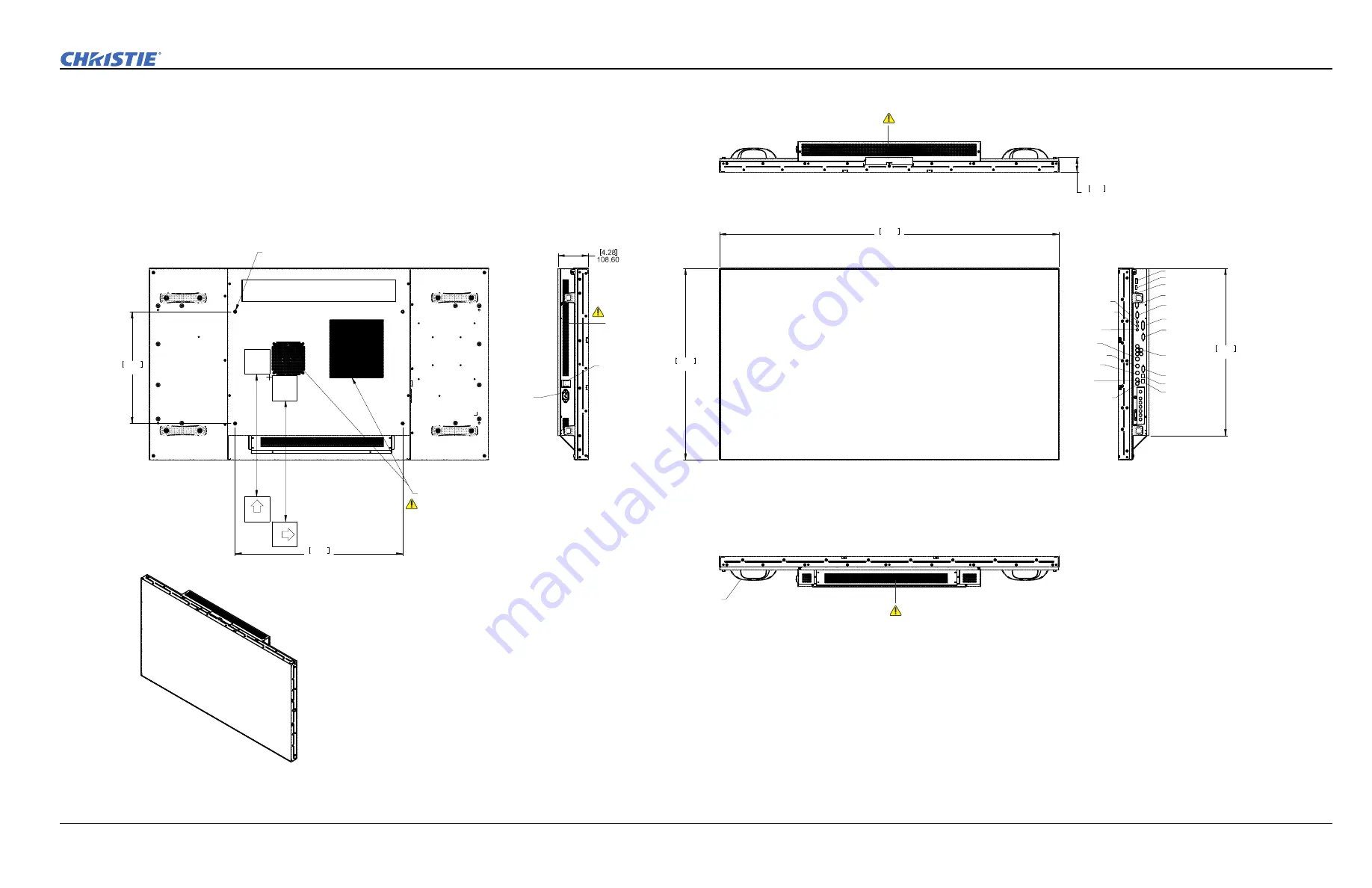
A.1 LCD Panel

M8 x 4 Mounting Holes,
Length of screw engagement: 10mm (min), 15mm (max)

15.75

400.00

23.62

600.00

This side UP

in landscape mode

T

h

is

 s

ide 
UP

in

 por

trai

t m

od

e

Exhaust & power supply location

DO NOT obstruct the air flow.

DO NOT obstruct 

the air flow.

DO NOT obstruct 

the air flow.

DO NOT obstruct 

the air flow.

Power

Connection

Power Switch
(Rocker Type)

2.12

53.90

47.85

1215.30

27.01

686.10

PC Audio In

Display Port
HDMI 1
HDMI 2

DVI-D In

VGA In

DVI-D Out

VGA Out

Comp Audio

RS232 In

RS485 In
RS485 Out

IR Extender

Line Out

S-Video

Video Out

Video In

L Video/S-V

Audio

R Video/S-V

Audio

23.59

599.30

Handle x4 locations

NOTE: Handles are hidden
in this view for clarity.

NOTE: Illustrations shown as third angle projection. Not to scale.

Summary of Contents for F100

Page 1: ...P100 Pedestal and F100 Frame I n s t a l l a t i o n M a n u a l 020 100734 02 ...

Page 2: ......

Page 3: ...P100 Pedestal and F100 Frame I n s t a l l a t i o n M a n u a l 020 100734 02 ...

Page 4: ...arately from regular waste Please dispose of the product appropriately and according to local regulations In the European Union there are separate collection systems for used electrical and electronic products Please help us to conserve the environment we live in GENERAL WARRANTY STATEMENTS For complete information about Christie s limited warranty please contact your Christie dealer In addition t...

Page 5: ...2 1 2 1 2 For F100 Frames Hardware Kit P N 000 102673 xx 2 2 2 1 3 For LCD Video Wall Mounts and LCD Panels 2 2 2 2 Kits Required 2 2 2 3 Tools and Hardware Required 2 2 2 4 Service and Support 2 2 2 5 Installation 2 3 2 5 1 Assemble the Pedestals 2 3 2 5 2 Install Frames onto Pedestals 2 5 2 5 3 Adding Additional Rows of F100 Frames 2 6 2 5 4 Install Video Wall Mount onto Frame 2 7 2 5 5 Install ...

Page 6: ......

Page 7: ...most extreme situations Warning symbols indicate a hazardous situation which if not avoided could result in death or serious injury Caution symbols indicate a hazardous situation which if not avoided could result in minor or moderate injury NOTICE Addresses practices not related to personal injury 1 3 Typographical Notations The following notations are used throughout this manual References to spe...

Page 8: ... on page 1 2 1 4 3 External Support Stacked pedestals frames and LCD panels can tip over and cause severe injury or damage when not properly secured The display wall must be supported during and after installation to a structurally sound surface such as a permanent wall or an installer approved free standing external support structure The P100 Pedestals F100 Frames and LCD panels must be stacked o...

Page 9: ...he sole and final responsibility for ensuring that the system is installed with due regard for all relevant safety considerations Installation steps are described in sequence and each step must be completed before moving on to the next 2 1 Components All major components required to assemble a complete display wall are packaged and shipped separately to the installation site This includes the LCD ...

Page 10: ...e P N 135 105107 xx FHD551 X LCD Panel P N 135 001102 xx Optional LCD Frame Trim 8ft P N 135 108100 xx 2 3 Tools and Hardware Required Level Phillips screwdriver 5mm allen key for attaching P100 Pedestals 6mm ball driver metric screwdriver for attaching F100 Frames 24mm open ended adjustable wrench for tightening locknut on pedestal feet 7mm open ended wrench for fastening extension hook 2x 10mm o...

Page 11: ...her aligning the front and rear edges 2 Using a level adjust the 3 pedestal feet by rotating them until the 2 pedestals are level on all sides and with each other Use a 24mm open ended adjustable wrench to tighten the lock nut on the feet once the required adjustment is made 3 Inspect the inside corners of the pedestal to confirm that the pedestal feet remain fully engaged in the pedestal If you c...

Page 12: ...to position and using a level adjust the height until the pedestal becomes level with the pedestals already in the row 7 Repeat steps 1 to 5 for each additional pedestal 8 Verify that the entire platform structure is level and that all rear edges between pedestals are flush NOTICE Apply downward pressure on the pedestal to ensure that the feet are flat to the floor 9 Do not completely tighten the ...

Page 13: ...wo can lift an LCD panel into position on the first row NOTICE Depending on the size of the wall assemble the frames starting at the center of the pedestal assemble working outwards to the end of each row 1 Position the first frame so that the 6 mounting points of the frame line up with the points on the pedestal 2 Loosely fasten the frame to the pedestal using 6 M8 socket head cap screws 12 washe...

Page 14: ...cond row beginning with the center and working outward Complete these steps for each frame in the next row a Using safe and approved lifting methods install the next frame over the lower frame approaching it from the back b Once the top frame is resting on the lower frame slide it forward until it is in position c Align the top and bottom frames until all edges are flush and the mounting holes are...

Page 15: ...ucture prevents the wall from tipping due to unforeseen circumstances When designing external support for a display wall consider Local building codes for specific requirements Size of the installation number of LCD panels being stacked Physical characteristics of the installation including weight center of gravity mounting hole location See Section A Mechanical Drawings for technical information ...

Page 16: ... xx 2 5 8 Optional Install Trim As an optional feature trim in the form of 8ft 2 4m magnetic strips can be applied to the sides of the display Each strip covers up to 3 frames in height 2 5 9 Optional Install Bracket Extension Hook To easily release individual panels installed into a display wall it is recommended the bracket extension hooks provided with the frame assembly are installed To instal...

Page 17: ...Pedestal and Frame Installation Manual A 1 020 100734 02 Rev 1 11 2011 A Mechanical Drawings ...

Page 18: ......

Page 19: ... air flow DO NOT obstruct the air flow DO NOT obstruct the air flow DO NOT obstruct the air flow Power Connection Power Switch Rocker Type 2 12 53 90 47 85 1215 30 27 01 686 10 PC Audio In Display Port HDMI 1 HDMI 2 DVI D In VGA In DVI D Out VGA Out Comp Audio RS232 In RS485 In RS485 Out IR Extender Line Out S Video Video Out Video In L Video S V Audio R Video S V Audio 23 59 599 30 Handle x4 loca...

Page 20: ...n corner adjustment knob in the mount is extended to 14mm 0 5 from its home position Panel Extended Out for Service LCD Panel P N 135 001102 Frame P N 135 105107 Pedestal P N 135 106108 General Notes 1 Refer to ML10 MP10 55 Spacer Kit Instruction Sheet P N 020 100728 xx for wall mount applications 2 Mounts frame pedestal shown here are for landscape orientation 3 Maximum stack height is 6 panels 4...

Page 21: ... Panel cap x2 6 82 173 2 8 24 209 General Notes 1 Views shown here are for pedestal and frame assembly for landscape orientation 2 Maximum adjustment possible using height adjustment knob is 25mm 1 3 Maximum range of adjustment on threaded foot along Y axis is 50mm 2 General Notes 1 Maximum adjustment possible using corner adjustment knob is 19mm 0 75 2 Fasten M8 screws with a maximum torque of 1 ...

Page 22: ......

Page 23: ......

Page 24: ...s ph 714 236 8610 Canada Kitchener ph 519 744 8005 United Kingdom ph 44 118 977 8000 France ph 33 0 1 41 21 00 36 Germany ph 49 2161 664540 Eastern Europe ph 36 0 1 47 48 100 Middle East ph 971 0 4 299 7575 Spain ph 34 91 633 9990 Singapore ph 65 6877 8737 Beijing ph 86 10 6561 0240 Shanghai ph 86 21 6278 7708 Corporate offices Worldwide offices ...

Reviews: