4-6
Entero RPMSP/RPMWU/RPMHD-LED01 Service Manual
020-100368-05 Rev. 1 (06-2012)
Section 4: Parts and Module Replacement
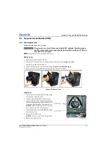
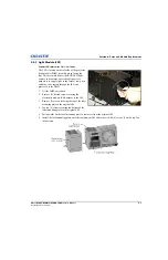
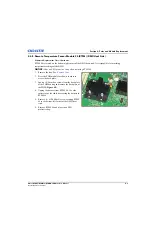
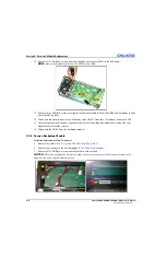
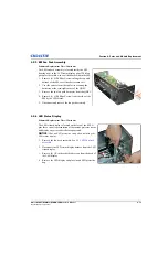
7. Remove (4) 4 mm hex screws securing the light module
to the PHM (2 on the top/2 on the bottom).
8. Carefully remove the light module and store in a safe
location.
NOTE:
When reinstalling the light module, make sure
the pins on the light module harness do not bend.
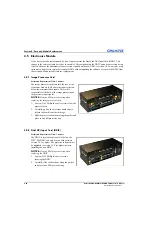
4.4.4 Quad DVI PHM Controller (QDPC)
Estimated Replacement Time: 5 minutes
The QDPC board provides an interface between the EM
and the FDWU/FDSP board in the PHM module to
route the video and communication signals from the
EM, as well as provide a separate line for
communications straight to the PHM. This board slots in
through the front of the PHM housing and connects
directly to the FDWU/FDSP board.
NOTICE:
Wear an ESD protective strap when replacing
the QDPC.
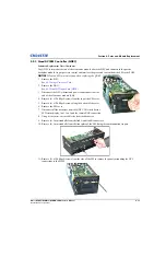
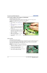
1. Remove the ethernet, power and DVI link A and B
harnesses from the faceplate connections.
2. Remove (5) 2.5 mm hex screws along the assembly
face plate.
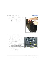
3. Slide the QDPC assembly out of the PHM housing
by pulling on the front handle, located on the
faceplate below the RJ45 connections.
4. Place in an ESD protective bag.
Summary of Contents for Entero RPMHD-LED01
Page 1: ...Entero RPMWU RPMSP RPMHD LED01 S E R V I C E M A N U A L 020 100368 05 ...
Page 2: ......
Page 3: ...Entero RPMWU RPMSP RPMHD LED01 S E R V I C E M A N U A L 020 100368 05 ...
Page 56: ......
Page 58: ......
Page 68: ......
Page 69: ......


