Chore-Time LIBERTY Feeding System Installation And Operator'S Manual Download Page 13

LIBERTY® Feeding System with Electronic Sensor (ES)

Installing the Suspension System

MF2426B

13

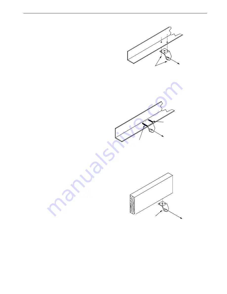
Ceiling Hook Installation

The ceiling hook may be used in a variety 
of installations. Depending on your 
ceiling or rafter type, install the Ceiling 
Hooks as shown in 

Figure 14

 - 

17

.

Steel Truss Installations

Wood Truss Installations

1523-80 4/2002

 Secure Ceiling Hook to truss

using self-drilling screws

through opposite holes

 Cable Travel

Figure 14.Steel Truss Ceiling Bracket Installation

1523-78 4/2002

 Cable Travel

 Weld Ceiling Bracket

to truss here

 Weld Ceiling Bracket

to truss here

Figure 15.Welded Steel Truss Ceiling Bracket Installation

Figure 16.Wood Truss Ceiling Bracket Installation

1523-79 4/2002

 Secure Ceiling Bracket to truss

using a 1/4" lag screw (not supplied)

through the center hole

 Cable Travel

Summary of Contents for LIBERTY Feeding System

Page 1: ...LIBERTY Feeding System with Electronic Sensor ES MF2426B January 2014 Installation and Operators Manual Installation and Operators Manual...

Page 2: ...xclusions may not apply to you This warranty gives the original purchaser specific legal rights You may also have other rights based upon your specific jurisdiction Compliance with federal state and l...

Page 3: ...Center Support 15 Assemble the Center Support and Feed Cone to grill 15 Feeder Line Assembly and Suspension 16 Feeder Pan Tube Assembly Process 16 Assemble and Suspend the Feeder Line 17 Installing th...

Page 4: ...5 150 Plastic Hopper Components 45 Hopper Boot Suspension Bracket optional For Single and Twin Boot Hopper Support Kit Part No 49358 46 Single Boot Components Part No 6822 47 Twin Boot Components Part...

Page 5: ...number Caution Warning and Danger Decals have been placed on the equipment to warn of potentially dangerous situations Care should be taken to keep this information intact and easy to read at all time...

Page 6: ...ifically state otherwise Ground all electrical equipment for safety All electrical wiring must be done by a qualified electrician in accordance with local and national electric codes Ground all non cu...

Page 7: ...lbs 2 kg REVOLUTION 12 MODEL S C2 Plus LIBERTY C2 Plus S C H2 H2 Plus 60 90 Broiler 6 lbs 2 7 kg REVOLUTION 8 12 C2 Plus C2 Plus S G Plus G Plus S C LIBERTY H2 H2 Plus 55 80 Broiler 7 lbs 3 1 kg REVO...

Page 8: ...der Control Pans should be at least 10 3 m from the Wall or Brood Curtain 5 Determine the distance to the Feeder Line from the Side Wall 6 Determine the distance from the Feed Hoppers to the End Wall...

Page 9: ...pproximately 17 lbs 7 7 kg per minute This rating is based on feed with a density of 40 lbs per cubic foot 640 kg per cubic meter Single phase 60 Hz and single and three phase 50 Hz Power Units are av...

Page 10: ...toward one side See Figure 5 2 Install a Cable Hook supplied in Hardware Package between the mounting bolt and Power Winch frame as shown in Figure 6 Installing the Suspension System Full Line Suspen...

Page 11: ...d within 3 9 m of the Power Unit This is in addition to the required Power Unit suspension If the Control Unit or Hopper does not come out directly under a truss fasten a pulley to a 2 x 8 50 x 200 mm...

Page 12: ...hooks 3 7 6 cm to each side of the line to prevent the cable clamps from catching the pulleys See Figure 12 Screw the hook into the truss the full length of the threads to prevent bending The opening...

Page 13: ...russ Installations 1523 80 4 2002 Secure Ceiling Hook to truss using self drilling screws through opposite holes Cable Travel Figure 14 Steel Truss Ceiling Bracket Installation 1523 78 4 2002 Cable Tr...

Page 14: ...is included to provide throwbacks on drops located beneath and near the winch Figure 18 shows a throwback cable arrangement 4 Begin installing suspension drops at the winch and proceed to the end of t...

Page 15: ...e Center Support and Feed Cone to grill 2 Guide the cone assembly through the grill cap be sure the cords pass through the cap See Figure 21 3 Align the threads and rotate the grill to the cone assemb...

Page 16: ...n Feeder Pan Tube Assembly Process 1 1 Slide one Feeder Pan Assembly per hole onto the auger tubes IMPORTANT Install all the feeders on the tubes in the same orientation 2 When sliding the feeders on...

Page 17: ...ontrol Tube 3 To achieve total feed drop out all along the system the Chore Time Logo should be centered at the crown of the tubes and all the Hangers should be installed as shown in Figure 27 4 Place...

Page 18: ...ulleys before raising the feeder line 7 Raise the feeder line to a convenient working height 8 With the feeder line suspended measure from the floor or ceiling to the auger tubes to level the system 9...

Page 19: ...pen top of the Feeder Boot flat See Figure 33 DO NOT INSTALL THE ANCHOR BEARING AND BEARING RETAINER AT THIS TIME Auger Installation Note Use extreme caution when working with the auger The auger is u...

Page 20: ...feet 1 8 m from the end of the boot uncoil the auger from the outside and feed the auger through the boot into the tubes 3 Push the auger into the tube in short strokes 4 Uncoil and handle the auger c...

Page 21: ...e auger then attach to the output shaft of the Power Unit as shown in Figure 35 Use the Driver Block to secure the auger to the Output Shaft 10 Attach the Anchor Plate and Gearhead Assembly to the Con...

Page 22: ...t the end of the boot See Figure 38 14 Auger stretch The auger needs to be stretched 7 180 mm per 100 30 m Example A 300 90 m feeder line requires 21 500 mm of stretch Beginning at the relaxed positio...

Page 23: ...sembly and auger securely 17 Slowly ease the auger back into the tube Use caution If the auger is allowed to spring back the bearing race may crack 18 Install the Bearing Retainer and fasten with a tu...

Page 24: ...ctuator Installation The LIBERTY Actuator is used to raise and lower the feed level cone Settings are 1 5 with the 1 being the lowest position grow out and 5 being the highest position brooding For tu...

Page 25: ...removed Mount the winch using the Lower Clamp Half 48487 and 1 4 20 x 2 5 Bolts 4404 4 included in the Actuator Kit See Figure 43 Springs at end of system Attach a Spring at each end of the system as...

Page 26: ...Tube Closure and Band Clamp See Figure 45 Installing Actuator Cable 1 Fasten one end of the Cable to the Spring at the end of the system as shown below 2 Route the Cable through the Feed Cones through...

Page 27: ...nsion MF2426B 27 3 Rotate the Actuator to the A position 4 Install the Center Clamp in the Actuator 5 Actuate the Cable to Stretch the Actuator Springs 1 25 mm Figure 48 Actuator Position Center Clamp...

Page 28: ...Lift cords to the Lift Cable Do not lift the Feed Cone off the support tabs The Cords must be routed toward the Actuator center of the brood area Lift the Feed Cone to connect Cords See Figure 52 for...

Page 29: ...anti roost cable Note If the cable is unrolled as shown in Figure 54 taking 5 loops of the coil with one hand then changing hands to remove 5 loops as it is unrolled it will lie flat during installat...

Page 30: ...trol unit after clamping the cable to the spring cut the cable about 8 to 10 200 to 250 mm longer than necessary Feed the end of the cable through the center of the spring around the first insulator o...

Page 31: ...ne Charger to the Anti Roost system Secure the Charger Wire to the Anti Roost cable using a cable clamp The anti roost system must be on a separate electrical circuit allowing the system to be disconn...

Page 32: ...New Feeder Lines Leave one feeder pan assembly off the feeder tube at the point where the Midline Control needs to be placed The feeder line can be assembled and suspended before attaching the Midline...

Page 33: ...the feeder tube in the control housing The feeder tube may have to be turned slightly to allow the pan to hang straight 4 Clamp the control in place by inserting tabs on the control top into the slot...

Page 34: ...64 2 Attach the Switch Box Assembly to the Feeder Tube with Hose Clamps as shown in Figure 64 3 Install a toggle switch out of reach of the birds to disconnect power to the Mid Line Control This allow...

Page 35: ...d becomes broken in To operate 5 Lower feeder lines so the feed pans are resting on the floor Although the major weight of the feeder lines will be on the floor do not remove all the weight from the s...

Page 36: ...first 5 days and thereafter 3 times a day or more as needed while the windows are open If it is not possible to operate the feeder manually 1 3 times a day during the brood time windows open then a t...

Page 37: ...l Pans utilize the manual ALL OUT FLOOD MANUAL OPERATION The feeder flood can be operated without cables and lift cords DAY 1 Raise the feed cone to the top of travel and rotate the feed cone this wil...

Page 38: ...B Wipe any debris off the magnet on the bottom Pipe Plug and reinstall Remove the side Pipe Plug and top Vent Plug C Set the power unit in the horizontal position D 2 Stage Gearheads Add approximately...

Page 39: ...the Time Delay For less time turn Time Delay Selector counter clockwise For more time turn Time Delay Selector clockwise To adjust the Safety Timer If No Safety Timer turn the Safety Timer adjustment...

Page 40: ...ar the auger may spring back into the tube BE CAREFUL WHEN WORKING WITH AUGER 4 Place a clamp or locking plier securely on the auger to prevent it from springing back into the auger boot 5 Loosen the...

Page 41: ...erloads frequently Oil on new auger loads motor excessively when feed is carried for first time Polish auger by running 50 lb 20 kg increments of feed out to pans Inadequate power reaching motors Chec...

Page 42: ...nic Sensor ES 42 MF2426B End Control With Electronic Sensor Wiring Electronic Sensor Control Wiring Mid Control with Electronic Sensor Wiring Wiring Diagrams 2426 004 10 13 End Control with Electronic...

Page 43: ...230 VOLTS 50 60 HZ FEEDER LINE MOTOR 220 230 VOLTS 50 60 HZ SINGLE PHASE TOGGLE SWITCH SPST 15 AMP NOT SUPPLIED MID LINE CONTROL UNIT 95 END CONTROL 96 1255 108 10 2000 K1 L2 T2 L3 T3 SINGLE PHASE C1...

Page 44: ...SES SHORT CIRCUIT PROTECTION NOT SUPPLIED CURRENT SENSOR AVAILABLE FEEDER LINE MOTOR 220 230 VOLTS 50 HZ THREE PHASE MID LINE CONTROL UNIT CONTROL BYPASS SWITCH NOT SUPPLIED M1 3 PH C1 END CONTROL 96...

Page 45: ...r cover 48675 4 Support cable assembly 2809 3 2809 3 5 Clevis pin 2797 1 2797 1 6 Boot adjuster bracket 2706 2706 7 Suspension angles 48679 48679 8 Suspension brace 48680 48680 9 Twist lock collar 490...

Page 46: ...For Single and Twin Boot Hopper Support Kit Part No 49358 6 1 2 3 4 5 Item Description Part No Single Boot Kit Part No Twin Boot Kit 1 Clevis Pin 5 16 x 1 2797 1 2797 1 2 Adjustment Bracket 2706 2706...

Page 47: ...Part No 1 Boot Weldment 3760 9 Anchor 38540 2 Tube Clamp 24063 10 5 16 18x7 8 Sock Hd Screw 47867 3 Cap 29373 11 Anchor and Bearing Ass y 39372 4 Outlet Tube 4556 12 Cannonball 3531 5 Sleeve 5648 13...

Page 48: ...Part No 1 Boot Weldment 3760 9 Anchor 38540 2 Tube Clamp 24063 10 5 16 18x7 8 Sock Hd Screw 47867 3 Cap 29373 11 Anchor and Bearing Ass y 39372 4 Outlet Tube 4556 12 Cannonball 3531 5 Sleeve 5648 13 C...

Page 49: ...3 Hole Tube 12 4 Hole Tube 12 5 Hole Tube 6854 1 6854 5 6854 4 6854 8 6854 7 6854 6 12 Standard Feeder Tube with Chick Holes 9 8 Hole Tube 10 8 Hole Tube 12 8 Hole Tube 12 10 Hole Tube 10 3 hole 3 EZ...

Page 50: ...RIPTION 1 52494 LIBERTY ACTUATOR ASSEMBLY 2 52495 ACTUATOR 3 52586 INSULATOR PULLEY ASS Y 4 48933 ACTUATOR BASE 5 4404 4 1 4 20 X 2 5 HEX BOLT 6 48487 CLAMP HALF 7 9126 TUBE CLOSURE 8 3527 BAND CLAMP...

Page 51: ...nual Brood Feeder without Lift Cords 52421 Silver LIBERTY Manual Brood Feeder without Lift Cords Item Description Part No 1 LIBERTY Grill 51630 51630 51630 51630 2 Feed Cone 51629 2 51629 3 51629 2 51...

Page 52: ...onic Sensor ES 52 MF2426B Poultry Trainers and Line Chargers Description Part No Poultry Trainer 110 V 60 Hz Poultry Trainer 220 V 50 60 Hz 29333 29325 Line Charger 110 V 60 Hz Line Charger 220 V 50 6...

Page 53: ...2 4642 4642 6 Gearhead 3261 5 3261 5 3261 11 3261 11 3261 5 7 Pipe Plug magnetic 30160 30160 30160 30160 30160 8 Pinion Assembly 5046 5046 5046 5046 5046 9 S Hook 4270 4270 4270 4270 4270 10 Motor 422...

Page 54: ...776 Switch Box Cover 11 24702 Switch Box 12 6968 1 Gasket 13 25064 Switch Box Mount 14 25433 Stop Panel 15 34018 10 24 Lock Nut 16 6723 Flat Washer 17 40749 Switch Box KEY PART NO DESCRIPTION 18 14434...

Page 55: ...t nut 43662 14 Date of mfg 2526 377 15 Relay 28904 16 Conduit fitting 26980 17 Gasket 6777 18 Deep junction box 42627 12 19 Mounting Terminal Box Cover 6956 20 10 24 hex screw 4416 7 21 Control bottom...

Page 56: ...75 Bolt 4416 4 8 10 32 lock nut 34019 9 10 flat washer 6723 10 Actuator pin 8757 11 10 Twin helix screw 28075 12 Midline control decal Silver Midline control decal Green 2529 933 2529 934 13 Plastic b...

Page 57: ...52398 5 LIBERTY feed cone Silver LIBERTY feed cone Green 51629 3 51629 2 6 Conduit nut 43662 7 Gasket 6635 8 Deep junction box 42627 1 Item Description Part No 9 10 24 Lock nut 34019 10 Liquid tight c...

Page 58: ...ring 1543 8 5 16 Flat Washer 2255 44 9 Midline Gear 2890 10 Flange Bushing 3252 11 Spirol Pin 2960 3 12 Bushing 2967 4 13 Washer 2955 1 14 Retaining Ring 2958 1 Item Description Part No 15 Drive Pinio...

Page 59: ...y Assembly 2014 5 Pulley 2500 6 3 16 Cable Clamp 732 7 Screw Hook 2041 8 Extendable Drive Tube 47637 9 Pulley Assembly 28429 10 Ceiling Hook 28550 11 Handle Shank 3148 Items 11 and 13 may be ordered a...

Page 60: ...l Page No Description of Change New Manual Contact your nearby Chore Time distributor or representative for additional parts and information Chore Time Group A division of CTB Inc PO Box 2000 Milford...

Reviews: