50
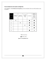
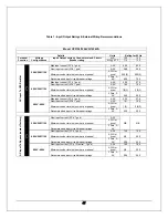
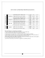
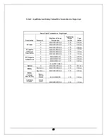
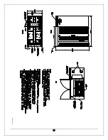
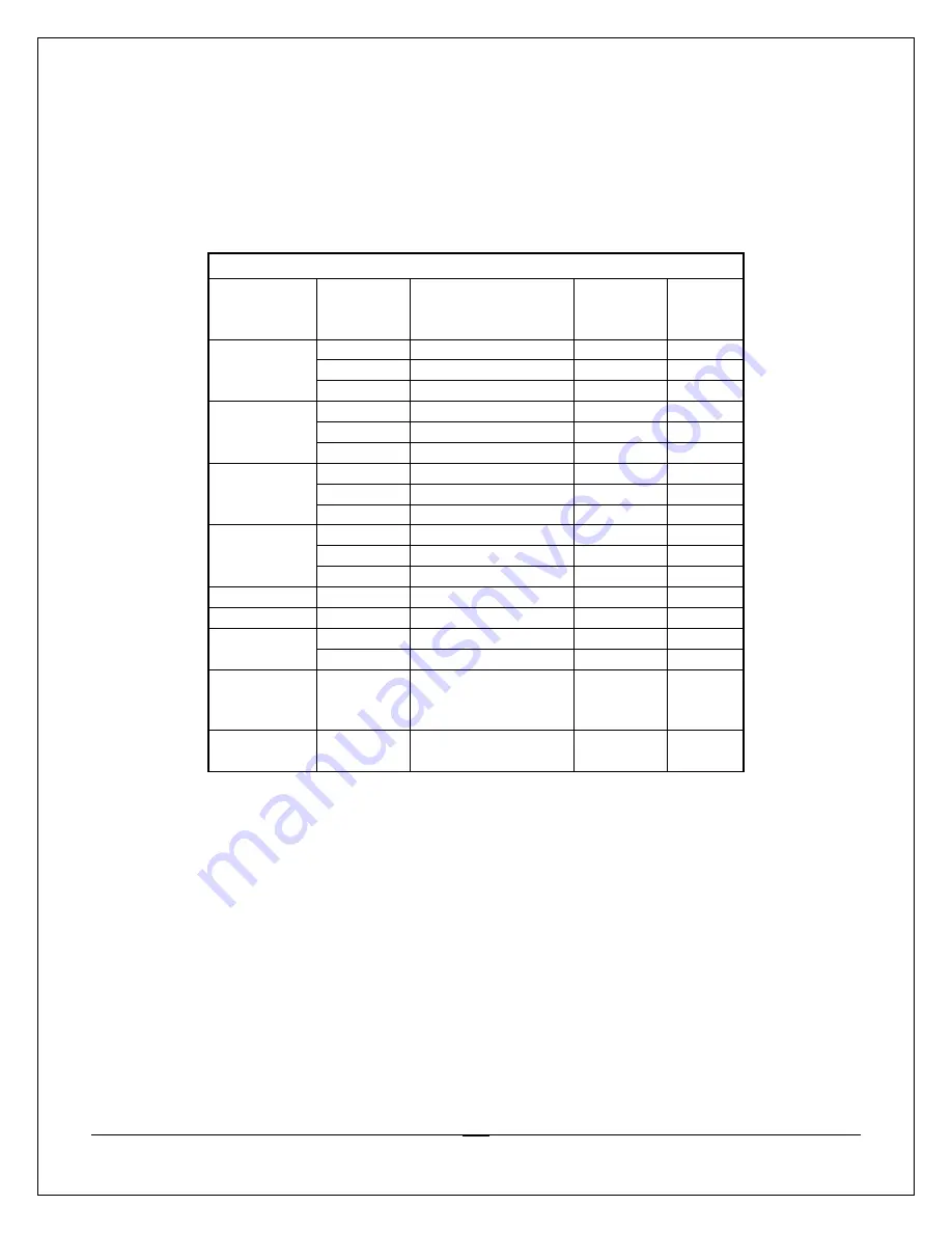
Table 3 – Input/Output and Battery Cabinet Wire Terminations for Dual Input
Power Cable Terminations - Dual Input
Termination Terminal
Wire Size of Clamp
Termination
Tightening
Torque
In.-lbs
Type
Screw
A
3/0-250MCM (2)
275
5/16 Hex
B
3/0-250MCM (2)
275
5/16 Hex
AC Input to
UPS Rectifier
C
3/0-250MCM (2)
275
5/16 Hex
A 4AWG-500MCM
(2) 375
1/2 Hex
B 4AWG-500MCM
(2) 375
1/2 Hex
AC Input to
UPS Input
Transformer
C 4AWG-500MCM
(2) 375
1/2 Hex
A 6AWG-350MCM 375
3/8
Hex
B 6AWG-350MCM 375
3/8
Hex
AC Input to
Bypass
C 6AWG-350MCM 375
3/8
Hex
A
6AWG-350MCM *
375
3/8 Hex
B
6AWG-350MCM *
375
3/8 Hex
AC Output to
Critical Load
C
6AWG-350MCM *
375
3/8 Hex
* (2 for 208V Output)
Neutral
N
6AWG-350MCM (4)
275
5/16 Hex
Positive (+)
6AWG-350MCM (2)
375
3/8 Hex
Battery
Negative (-)
6AWG-350MCM (2)
375
3/8 Hex
Battery
Cabinet
Ground Only
Battery
Cabinet
Ground 6AWG-350MCM 375 3/8
Hex
Customer
Ground
Ground
(Earth)
2AWG-600MCM (4)
500
1/2 Hex
Note:
•
The cable sizes are defined as minimum cable sizes
•
Input and output conductors are based on NEC 310-16 for insulated copper conductors rated at 75°C in ambient
temperature of 40°C (104°F).
•
Grounding conductors are based on NEC 250-95 for copper wire.
•
UPS input and output cables should be run in separate conduits.
•
It is recommended that the external cables and protection be selected for the highest possible rating of UPS kVA.
•
For dual input, connect the mains supply cables to the UPS input terminals A, B, C. Connect the Bypass input to
input terminals A, B, C, N. For single input, connect main input and bypass to the same input source. Connect the
load to UPS output terminals A, B, C, and N. The minimum conductor cross sections apply for maximum currents.
•
Should there be any variation in the conditions it will be necessary to verify whether the cable dimensions satisfy the
requirements of NEC. In cases where the cables are so long that they cause a drop in voltage of >3%, a larger
dimension shall be selected.

