


200 Series General Purpose Vector AC Drive Chapter 6 Key Functional Parameter Explanation In Detail
63
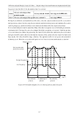
As shown in the figure above, in this control mode, when the SB1 button is closed, press the SB2 button
and the drive starts to run . K disconnects the drive for forward rotation, K closes the drive for reverse
rotation; the drive stops when the SB1 button is disconnected. During normal startup and operation, the
SB1 button must be kept in the closed state, and the command of the SB2 button will take effect at the
edge of the closing action.
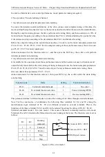
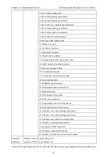
Terminal command mode 3: three- wire control 2, in this mode , S3 is the enable terminal, and the start
command is controlled by S1 and S2 respectively.
The function code set is as below:
Function code
Name
Set value
Function description
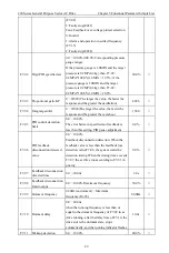
F0-13
Terminal command mode
3
Three- wire 2
F4-00
S1 terminal function selection
1
Forward running(FWD)
F4-01
S2 terminal function selection
2
Reverse running(REV)
F4-02
S3 terminal function selection
3
Three-wire running control
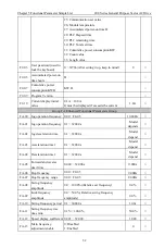
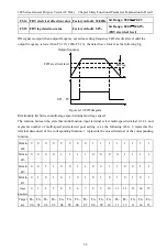
SB2
SB1
SB3
S1 Forward RUN
(
FWD
)
S3 RUN enabled
S2 Reverse RUN
(
REV
)
COM Digital common
Forward Button
Stop button
Reverse button
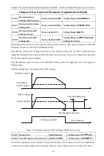
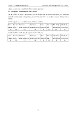
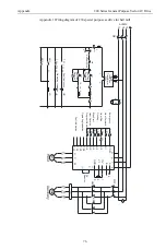
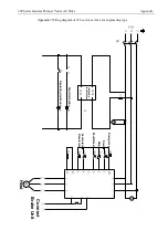
Figure 6-7 Three-wire control Mode 2
As shown in the figure above, in this control mode, when the SB1 button is closed, press the SB2 button,
the drive will forward running, press the SB3 button and the drive will reverse running. When the SB1
button is disconnected, the drive will stop immediately. During normal startup and operation, the SB1
button must be kept in the closed state. The SB2 and SB3 button commands will take effect at the edge of
the closing action. The running state of the drive is subject to the last key action of the 3 buttons.
Terminal command mode 4: three-wire control mode 3, The function is the same as the three-wire control
mode 2, except that the three-wire running terminal is normally open (stop when closed).
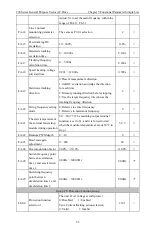
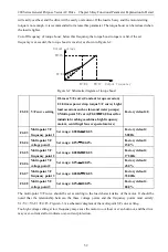
F4-27 Set
length
Set range: 0m
~
32000m
Factory default: 1000m
F4-28 Actual
length
Set range: 0m
~
3200m
Factory default: 0m
F4-29 Number of pulses per meter
Set range: 0.1
~
3200.0
Factory default: 100.0
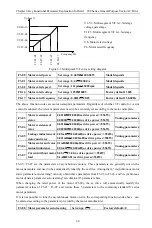
The above function codes are used for fixed-length control. The length information needs to be collected
by the multifunctional digital input terminal. The number of pulses sampled by the terminal is divided by
the number of pulses per meter F4-29, and the actual length F4-28 can be calculated. When the actual
length exceeds the set length F4-27, the multifunctional digital DO outputs the "length reached" ON
signal.
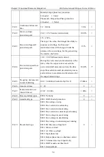
In the process of fixed length control, the length count reset operation can be performed by the
multi-function input terminal (S function selection is 21). For details, please refer to the settings of
H4-00
~
H4-05. In the application, the corresponding input terminal function needs to be set to "length


