Chapter 3 Mechanical and Electrical Installation 200 Series General Purpose Vector AC Drive
28
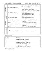
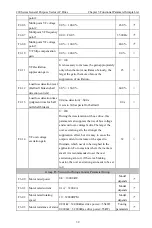
A
nal
og o
utput
FM1—GND Analog output 1
Output voltage or current could be selected by the JP9
jumper of the control board.
Output voltage range: DC 0V
~
10V;
Output current range: DC 0
~
20mA.
FM2—GND Analog output 2
Output voltage or current could be selected by the JP19
jumper of the control board.
Output voltage range: DC 0V
~
10V;
Output current range: DC 0
~
20mA.
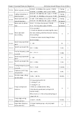
Dig
ita
l
out
put
SP1—24V Digital output
Open collector output
Output voltage range: DC 0V
~
24V
Max output current is 50mA
R
elay out
pu
t
TA0-TB0
TA0-TC0
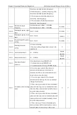
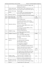
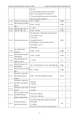
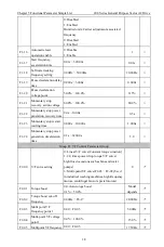
Normal closed/ open
terminals
Relay output, TA0-TB0 normal closed,TA0-TC0
normal open.
Contact capacity: AC 250V/3A,DC 30V/1A
TA1-TB1
TA1-TC1
Normal closed/open
terminals
Relay output, TA1-TB1 normal closed,TA1-TC1
normal open.
Contact capacity: AC 250V/3A,DC 30V/1A
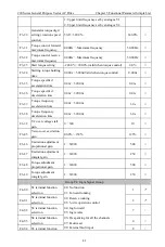
C
om
m
unic
ati
on
termi
na
l
485-
485+
RS485 hardware circuit
Support standard MODBUS communication
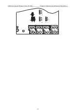
2)Explain of jumper
Jumper No.
Description
JP2
Analog input V2 signals type selection
Select DC 0V
~
10V or 4
~
20mA input
JP9
Analog output FM1 signals type selection
Select DC 0V
~
10V or 0
~
20mA output
JP19
Analog output FM2 signals type selection
Selection DC 0V
~
10V or 0
~
20mA output
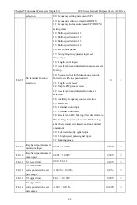
3)Diagram of jumper position:

