I N S T A L L A T I O N I N S T R U C T I O N S
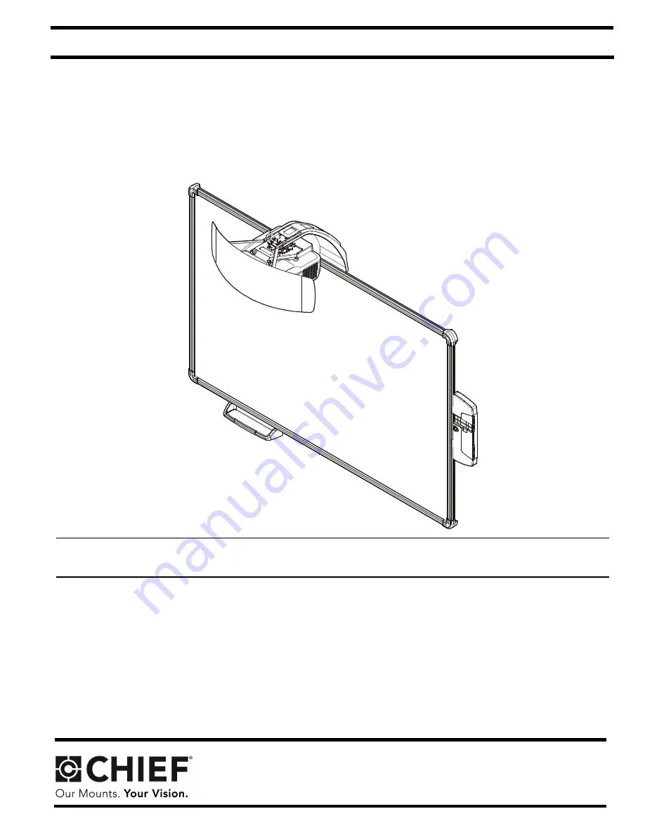
All-in-One System
Spanish Product DescriptionGerman Product Description
Portuguese Product Description
Italian Product Description
Dutch Product Description
French Product Description
AN1 Series
Page 1: ... N I N S T R U C T I O N S All in One System Spanish Product Description German Product Description Portuguese Product Description Italian Product Description Dutch Product Description French Product Description AN1 Series ...
Page 2: ... in serious personal injury damage to equipment or voiding of factory warranty It is the installer s responsibility to make sure all components are properly assembled and installed using the instructions provided WARNING Failure to provide adequate structural strength for this component can result in serious personal injury or damage to equipment It is the installer s responsibility to make sure t...
Page 3: ...Installation Instructions AN1 Series 3 DIMENSIONS DIMENSIONS INCHES MILLIMETERS ...
Page 4: ... Chave de bocas Chiave a punte aperte Steeksleutel Clé à fourche By Hand A mano Von Hand Com a mão A mano Met de hand À la main Hex Head Wrench Llave de cabeza hexagonal Sechskantschlüssel Chave de cabeça sextavada Chiave esagonale Zeskantsleutel Clé à tête hexagonale Pencil Mark Marcar con lápiz Stiftmarkierung Marcar com lápis Segno a matita Potloodmerkteken Marquage au crayon Drill Hole Perfora...
Page 5: ...ctor mount A 4 B 4 Toggler anchor kit C 4 1 4 20 x 1 3 4 D 4 1 4 E 4 1 4 20 F 8 4 cable tie 1 4 x 2 1 2 Hilti Hud L 8 x 60 G 4 10 24 x 3 8 H 6 10 24 x 3 8 J 4 M4 x 10mm K 8 8 x 1 2 L 6 8 9 x 1 1 2 N 2 4 24 x 1 4 P 6 Screen bracket W 1 Marker set U 1 X 1 Marker tray Y 1 Left valence bracket Z 1 Right valence bracket BB 1 Valence AA 1 RF Cable Install Hardware Kit Control panel assembly M 6 Toggler ...
Page 6: ...or size at location marked in Step 3 See Figure 1 and follow fastener information appropriate for wall type located in Table 1 IMPORTANT See Fastener Installation Methods at end of Installation Instructions for details on installing product into various wall types Table 1 Fastener Information WALL TYPE PILOT HOLE FASTENERS see PARTS drawing Drywall only boom attach only Steel studs 1 2 1 4 20 Togg...
Page 7: ... projector mount V into vertical portion of wall bracket S See Figure 4 7 Install and tighten four 10 24 x 3 8 Phillips flat head screws G through wall bracket S into boom projector arm V See Figure 4 8 Determine location of studs behind drywall and mark a minimum of two locations for wall bracket attachment over studs NOTE For concrete walls mark at least two locations for attachment a minimum of...
Page 8: ...inimum of 2 brackets along bottom of screen and locate brackets as close to outer corners as possible Remaining brackets may be used along sides of screen as desired Figure 6 4 Lift and remove screen from wall bracket 5 Install screen brackets P using Wood steel studs one 8 9 x 1 1 2 wood screw L into top of each bracket slot and slightly lower than marked location See Figure 6 Concrete wall one 8...
Page 9: ...een frame with tab placed behind screen See Figure 10 3 Slide control panel assembly up along side of screen assembly to the desired height See Figure 10 Figure 10 4 Determine attachment location on wall See Figure 10 5 Mark attachment hole through slot in control panel assembly U See Figure 10 6 Slide control panel assembly up or down away from marked hole 7 Drill one pilot hole see Table 1 for s...
Page 10: ...ead screws N Do NOT over tighten See Figure 12 6 Attach all cables including RF cable AA to control pad following instructions included with projector control pad IMPORTANT Connect cables BEFORE replacing control pad cover 7 Use cable ties F as necessary to secure the cables within control panel See Figure 12 8 Replace top cover onto control pad See Figure 12 Figure 12 9 OPTIONAL The tab in the co...
Page 11: ... pitch adjustment locking screw using a 2 Phillips screwdriver See Figure 14 2 Turn pitch micro adjustment screw right or left using a 2 Phillips screwdriver until image is properly aligned on target 3 Tighten pitch adjustment locking screw using a 2 Phillips screwdriver Figure 14 Roll Adjustment 1 Loosen roll adjustment locking screw using a 2 Phillips screwdriver See Figure 15 2 Turn roll micro ...
Page 12: ...ight brace on back of valence BB and fasten with two 10 24 x 3 8 Phillips pan head machine screws H See Figure 18 2 Align left valence bracket Y along outside of left brace on back of valence BB and fasten with two 10 24 x 3 8 Phillips pan head machine screws H See Figure 18 Figure 18 3 Slide the valence BB with attached brackets into the boom mount V sliding brackets under tabs in boom See Figure...
Page 13: ...hing side to side snapping off straps level with flange of plastic cap See Figure 22 Figure 22 5 Line up anchor with attachment point 6 Insert 1 4 20 x 1 3 4 Phillips pan head screw C through 1 4 washer D corresponding mounting hole in product and into anchor E and tighten until flush against product DO NOT over tighten See Figure 23 Figure 23 Wood Stud NOTE Refer to Table 1 for appropriate hardwa...
Page 14: ...1 for appropriate hardware and pilot hole sizes for various wall types 1 Install an anchor B into each pilot hole using a hammer making sure that the anchor is flush with the wall 2 Use one 1 4 x 2 1 2 lag bolt A through product into each anchor in wall Figure 25 1 2 A B ...
Page 15: ...Installation Instructions AN1 Series 15 ...
Page 16: ...klinstraat 14 6003 DK Weert Netherlands P 31 0 495 580 852 F 31 0 495 580 845 Asia Pacific A Office No 1 on 12 F Shatin Galleria 18 24 Shan Mei Street Fotan Shatin Hong Kong P 852 2145 4099 F 852 2145 4477 Chief Manufacturing a products division of Milestone AV Technologies 8800 002469 Rev00 2013 Milestone AV Technologies a Duchossois Group Company www chiefmfg com 09 13 ...