background image

Page 11

For technical questions, please call 1-888-866-5797.

Item 64518 


Sa

FE

ty

Op

Era

ti

O

n

Maint

Enanc

E

SE

tup

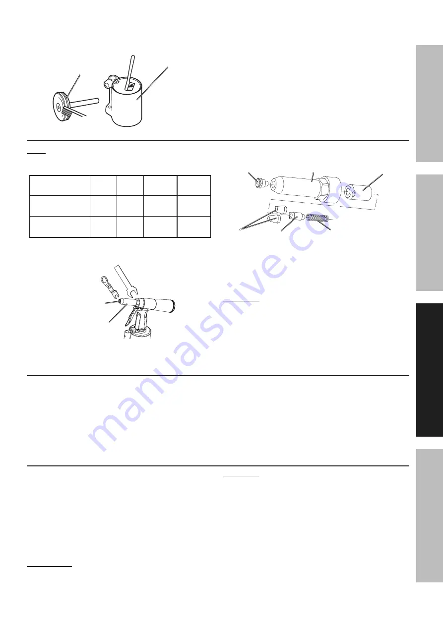
5.  Apply silicone based grease (not included) 

to the inner wall of the Air Cylinder 

and the Piston Head O-Ring.

piston Head

O-ring

air cylinder

6.  Replace the Piston Head.

configuring For rivet Size:

note:

 Tool comes with a 1/4″ (1A) Nosepiece 

with its appropriate matched hardware 

installed as shown in the table below.

nosepiece

Jaw 

case

Jaws

Jaw 

pusher

pusher 

Spring

1/8" (1E) 

5/32" (1D)

6-1A

7A

8A

10-1

3/16" (1C) 

1/4" (1A)

6-1

7

8

10

1.  Use the included Wrenches to remove 

the Nosepiece and Outer Cylinder.

Outer 

cylinder

nosepiece

2.  Unscrew the Jaw Case from the Jaw Cylinder.

3.  Remove the Jaw Pusher and Jaws from the Jaw 

Case, and remove the Spring from the Jaw Cylinder.

nosepiece (1) Outer cylinder (11)

Jaw case (6)

Jaw (7) Jaw pusher (8) Spring (10)

4.  Reassemble with the correct hardware to 

match the selected Nosepiece size.  When 

reassembling the Jaw Case, line up the 

wedge on the Jaw Pusher’s head in-between 

the Jaws, pushing them slightly apart.

important:

  When reassembling the Jaw Case, 

line up the wedge on the Jaw Pusher’s head 

in-between the Jaws, pushing them slightly 

apart.  Reference steps 7 through 10 in the 

User-Maintenance Instructions on page 12.

Workpiece and Work area Set up

1.  Work areas must be clean and well-lit.  

Do not allow access by children or pets 

to prevent distraction and injury.

2.  Route the air hose to the work area to 

minimize tripping hazards, hose damage, 

etc.  The air hose must be long enough to 

allow free movement while working.

3.  Secure loose workpieces using a vise or clamps 

(not included) to prevent movement while working.

4.  Remove hazardous objects (such as utility lines or 

foreign objects) that present a hazard while working.

General Operating instructions

1.  If an automatic oiler is not used, add a few drops of 

Pneumatic Tool Oil to the airline before use, with a 

few drops more after each hour of continual use.

2.  Screw the Pin Cap onto the Riveter Housing 

and tighten firmly.  Turn the slot in the Pin Cap 

upward to avoid spilling used rivet pins.

3.  Depending on the rivet pin size, install the 

correct hardware for that rivet size as described 

above under 

configuring For rivet Size:

.

iMpOrtant:  

When drilling rivet holes in a 

workpiece, use the same diameter drill bit as 

the outer diameter of rivet being used.

cautiOn!

  Verify the work surface has 

no hidden utility lines before drilling.
4.  Attach an air hose to the Air Inlet of the Riveter.
5.  Turn on the air compressor, and set its regulator to 

the needed pressure.  

Do not exceed the tool’s  

maximum air pressure rating.

6.  Insert the small end of a rivet fully through 

the Nosepiece.  

cautiOn! Keep clear of 

the trigger when inserting rivets.

7.  Insert the rivet through the predrilled 

hole in the workpiece.

Summary of Contents for 64518

Page 1: ...When unpacking make sure that the product is intact and undamaged If any parts are missing or broken please call 1 888 866 5797 as soon as possible Copyright 2018 by Harbor Freight Tools All rights reserved No portion of this manual or any artwork contained herein may be reproduced in any shape or form without the express written consent of Harbor Freight Tools Diagrams within this manual may not ...

Page 2: ...t in minor or moderate injury Addresses practices not related to personal injury IMPORTANT SAFETY INSTRUCTIONS INSTRUCTIONS PERTAINING TO A RISK OF FIRE ELECTRIC SHOCK OR INJURY TO PERSONS WARNING When using tools basic precautions should always be followed including the following General To reduce the risks of electric shock fire and injury to persons read all the instructions before using the to...

Page 3: ...s an increased risk of electric shock if your body is grounded 11 Explore the workpiece to avoid contact with hidden wiring Thoroughly investigate the workpiece for possible hidden wiring before performing work Contact with live wiring will shock the operator Tool Use and Care 1 Use clamps or another practical way to secure and support the workpiece to a stable platform Holding the work by hand or...

Page 4: ... the air source has been adjusted to the rated air pressure or within the rated air pressure range 2 Never use oxygen carbon dioxide combustible gases or any bottled gas as an air source for the tool Such gases are capable of explosion and serious injury to persons SAVE THESE INSTRUCTIONS Symbols and Specific Safety Instructions Symbol Definitions Symbol Property or statement PSI Pounds per square...

Page 5: ...rated to handle the forces exerted by this tool during operation Other accessories not designed for the forces generated may break and forcefully launch pieces 3 Attach all accessories properly to the tool before connecting the air supply A loose accessory may detach or break during operation 4 Obey the manual for the air compressor used to power this tool 5 Install an in line shutoff valve to all...

Page 6: ...intenance Setup Functional Description Specifications Maximum Air Pressure 90 PSI Air Inlet 1 4 18 NPT Maximum Air Consumption 1 7 CFM 90 PSI Rivet Pin Capacity 1 4 3 16 5 32 1 8 Nosepiece change needed Components and Controls Air Inlet Nosepiece Pin Cap Outer Cylinder Trigger Lanyard Loop ...

Page 7: ...quick coupler will make operation more efficient but are not required WARNING TO PREVENT SERIOUS INJURY FROM ACCIDENTAL OPERATION Do not install a female quick coupler on the tool Such a coupler contains an air valve that will allow the air tool to retain pressure and operate accidentally after the air supply is disconnected Note Air flow and therefore tool performance can be hindered by undersize...

Page 8: ...ir Hose Connects air to tool B Filter Prevents dirt and condensation from damaging tool or workpiece C Regulator Adjusts air pressure to tool D Lubricator optional For air tool lubrication E Coupler and Plug Provides quick connection and release F Leader Hose optional Increases coupler life G Air Cleaner Dryer optional Prevents water vapor from damaging workpiece H Air Adjusting Valve optional For...

Page 9: ...ibration reduction E Main Air Line 3 4 minimum recommended Distributes air to branch lines F Ball Valve To drain moisture from system G Branch Air Line 1 2 minimum recommended Brings air to point of use H Air Hose Connects air to tool I Filter Prevents dirt and condensation from damaging tool or workpiece J Regulator Adjusts air pressure to tool K Lubricator optional For air tool lubrication L Cou...

Page 10: ...ny control or component in a way not specifically explained within this manual Improper adjustment can result in tool failure or other serious hazards Swivel Air Fitting 1 Attach the Swivel Air Fitting to the Air Cylinder of the Riveter before use Air Cylinder Swivel Air Fitting Pin Cap 1 Attach the Pin Cap to the Grip Housing of the Riveter before use Grip Housing Pin Cap Priming 1 Use the Wrench...

Page 11: ...eas must be clean and well lit Do not allow access by children or pets to prevent distraction and injury 2 Route the air hose to the work area to minimize tripping hazards hose damage etc The air hose must be long enough to allow free movement while working 3 Secure loose workpieces using a vise or clamps not included to prevent movement while working 4 Remove hazardous objects such as utility lin...

Page 12: ...e tool to operate more safely and will also reduce wear on the tool 4 Quarterly every 3 months Tool Disassembly Cleaning and Inspection Have the internal mechanism cleaned inspected and lubricated by a qualified technician Jaw Cleaning and Replacement 1 Unscrew and remove the Outer Cylinder using the Wrench 2 Unscrew and remove the Jaw Case from the Jaw Cylinder 3 Remove the Jaws from the Jaw Case...

Page 13: ...e Lock Nut against the Jaw Cylinder using the Wrench Gauge 10 Replace the Outer Cylinder and tighten using the Wrench Troubleshooting Problem Possible Causes Likely Solutions Jaws slipping Worn or damaged Jaws Replace Jaws Jaws will not open 1 Loose Nosepiece 2 Dirty Jaws 1 Tighten Nosepiece 2 Clean Jaws Stroke is too short 1 Rivet pin not properly inserted into Riveter 2 Low hydraulic fluid 3 Riv...

Page 14: ...1 43A Valve Pusher O Ring 1 44 Valve Pusher 1 44A Valve Spring 1 45 Valve 1 45A Valve Collar 1 45B O Ring 1 46 Valve Spring 1 47 Swivel Air Fitting 1 51 O Ring 1 52 Valve Cap 1 59 Pin Cap 1 60 O Ring 1 61 Pin Cap Adapter 1 Parts List and Diagram PLEASE READ THE FOLLOWING CAREFULLY THE MANUFACTURER AND OR DISTRIBUTOR HAS PROVIDED THE PARTS LIST AND ASSEMBLY DIAGRAM IN THIS MANUAL AS A REFERENCE TOO...

Page 15: ...4518 Safety Operation Maintenance Setup Assembly Diagram 1A 11 6 1 7 8 10A 20 21 59 18 17 16 6 2 10 9 12 37 40 41 39 42 15 25 26 25 43A 44 44A 45A 45B 28 27 45 46 51 52 30 1 31 30 2 30 3 32 33 24 43 14 13 14 29 38 35 36 47 19 19 1 60 61 1C 1D 1E 1F 6 1A 7A 8A 10 1 1B ...

Page 16: ...damages so the above limitation of exclusion may not apply to you THIS WARRANTY IS EXPRESSLY IN LIEU OF ALL OTHER WARRANTIES EXPRESS OR IMPLIED INCLUDING THE WARRANTIES OF MERCHANTABILITY AND FITNESS To take advantage of this warranty the product or part must be returned to us with transportation charges prepaid Proof of purchase date and an explanation of the complaint must accompany the merchand...

Reviews: