REAR SUSPENSION AND DRIVE LINE 4-24
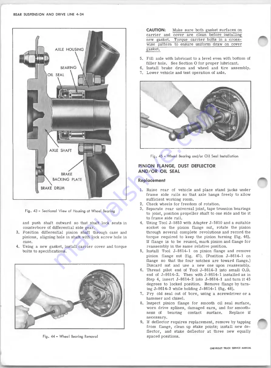
Fig . 43 - Sectional V ie w of Housing at W h eel Bearing
and push shaft outward so that shaft lock seats in
counterbore of differential side gear.
3.
Position differential pinion shaft through case and
pinions, aligning hole in shaft with lock screw hole in
case.
4. Using a new gasket, install carrier cover and torque
bolts to specifications.
F ig . 4 4 - W heel Bearing Removal
CAUTION:
Make sure both gasket surfaces on
carrier and cover are clean before installing
new gasket. Torque carrie r bolts in a cross
wise pattern to ensure uniform draw on cover
gasket.
5. F ill axle with lubricant to a level even with bottom of
filler hole. See Section O for proper lubricant.
6
. Install brake drum and wheel and tire assembly.
7. Lower vehicle and test operation of axle.
F ig .
45 -
W h eel Bearing and/or O il Seal Installation
PINION FLANGE, DUST DEFLECTOR
AND/OR OIL SEAL
Replacement
1. Raise rear of vehicle and place stand jacks under
frame side rails so that axle hangs freely to allow
sufficient working room.
2. Check wheels for freedom of rotation.
3. Separate rear universal joint, tape trunnion bearings
to joint, position propeller shaft to one side and tie it
to frame side rail.
4. Using Tool J-5853 with Adapter J-5810 and a suitable
socket on the pinion flange nut, rotate the pinion
through several complete revolutions and record the
torque required to keep the pinion turning (fig. 46).
If flange is to be reused, mark pinion and flange for
reassembly in the same relative position.
5. Install Tool J-8614-1 on pinion flange and remove
pinion flange nut (fig. 47). (Position J-8614-1 on
flange so that the four notches are toward flange.)
Discard nut and use a new one upon reassembly.
6
. Thread pilot end of Tool J-8614-3 into small O.D.
end of J-8614-2. Then with J-8614-1 installed as in
Step 4, insert J-8614-2 into J-8614-1 and turn it 45
degrees to locked position. Remove flange by turn
ing J-8614-3 while holding J-8614-1 (fig. 48).
7. Pry old seal out of bore, using a screwdriver or a
hammer and chisel.
8
. Inspect pinion flange for smooth oil seal surface,
worn drive splines, damaged ears, and for smooth
ness of
bearing
contact surface.
Replace if
necessary.
9. If deflector requires replacement, remove by tapping
from flange, clean up stake points; install new de
flector, and stake deflector at three new equally
spaced positions.
CHEVROLET TRUCK SERVICE M ANUAL
Summary of Contents for 10 Series 1967
Page 1: ...CHASSIS V3 a n s W U gw...
Page 2: ......
Page 28: ......
Page 80: ...BODY IB 18 Fig 41 Exploded View of Level Ride Seat CHEVROLET TRUCK SERVICE MANUAL...
Page 89: ...BODY IB 27 CHEVROLET TRUCK SERVICE MANUAL...
Page 105: ...BODY IB 43 Fig 94 Check Link Assembly Typical CHEVROLET TRUCK SERVICE MANUAL...
Page 117: ...BODY IB 55 Fig 116 A uxiliary Seat CHEVROLET TRUCK SERVICE MANUAL...
Page 121: ...Fig 4 1 0 3 0 Series Truck Frame...
Page 122: ...Fig 5 4 0 6 0 Single A xle Truck Frames Exc T ilt Cab FRAME 2 4...
Page 124: ...CHEVROLET TRUCK SERVICE MANUAL 1 Ficu 7 4 0 6 0 Series T ilt Cab Truck Frames FRAME 2 6...
Page 228: ...BRAKES 5 12 TD 50 60 Fig 23 Parking Brake Cables T Models CHEVROLET TRUCK SERVICE MANUAL...
Page 280: ......
Page 324: ...I I...
Page 336: ...ENGINE FUEL 6M 12 CHEVROLET TRUCK SERVICE MANUAL...
Page 342: ......
Page 348: ......
Page 386: ......
Page 393: ...CHEVROLET TRUCK SERVICE MANUAL CLUTCHES AND TRANSMISSIONS 7 7...
Page 472: ...STEERING 9 18 Fig 31 Typical Power Steering Hose Routing CHEVROLET TRUCK SERVICE MANUAL...
Page 474: ...w j...
Page 486: ......
Page 500: ...1...
Page 502: ...l c t r iC al 12 2...
Page 568: ......
Page 576: ......
Page 580: ...1...
Page 587: ...SPECIFICATIONS 7 ENGINE SECTION 6 8 25 1 on CE TE400 Series CHEVROLET TRUCK SERVICE MANUAL...
Page 590: ...SPECIFICATIONS 10 ENGINE TORQUES CHEVROLET TRUCK SERVICE MANUAL...


