background image

SAFETY INSTRUCTIONS 


PRECAUTIONARY DEFINITIONS 

The precautionary instructions found in this section and 
throughout this manual are indicated by specific symbols. 
Understand these symbols and their definitions before 
operating this equipment. The definitions of these 
symbols are as follows: 

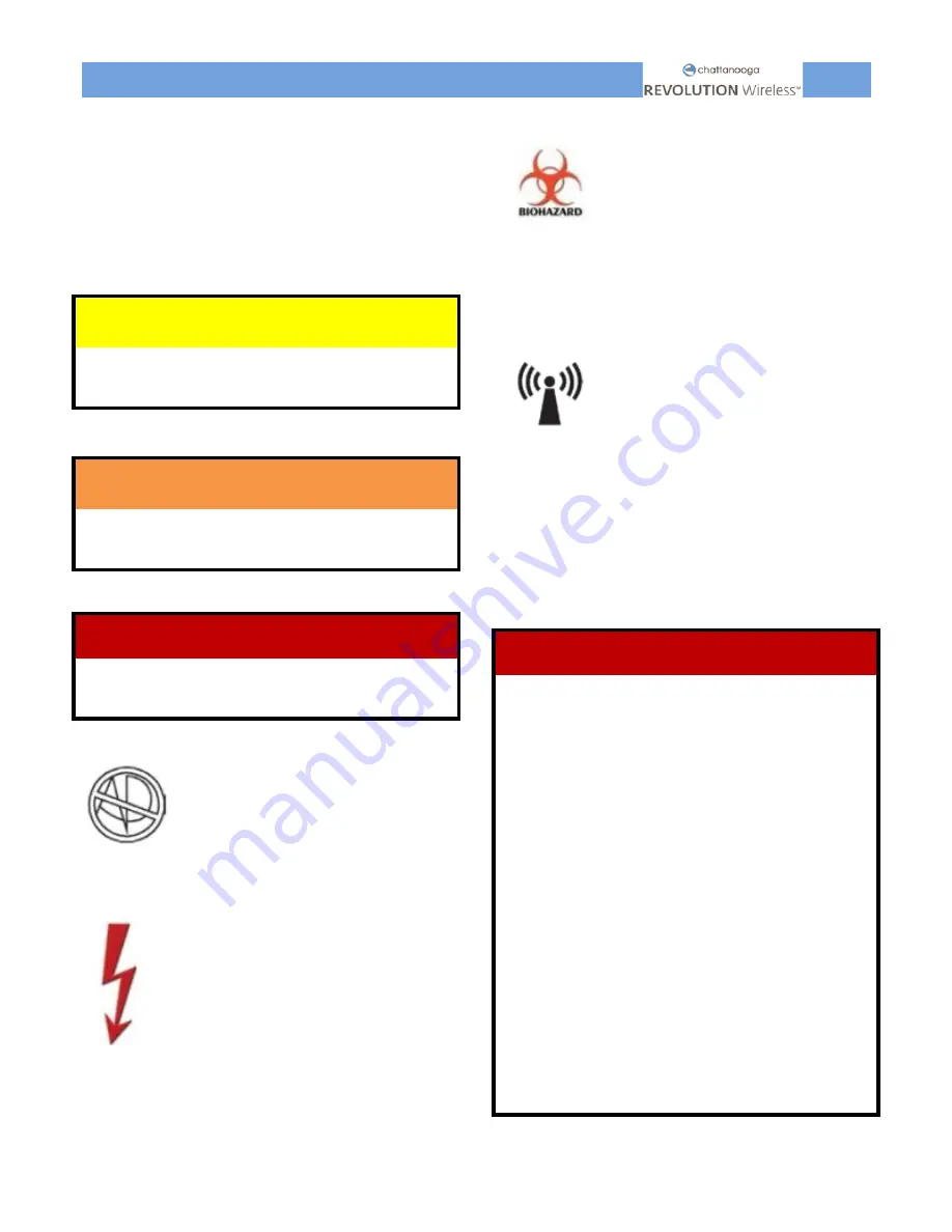
CAUTION 

Text with a “CAUTION” indicator will explain possible 

safety infractions that could have the potential to cause 

minor to moderate injury or damage to equipment. 


WARNING 

Text with a “WARNING” indicator will explain possible 

safety infractions that will potentially cause serious injury 

and equipment damage. 


DANGER 

Text with a “DANGER” indicator will explain possible 

safety infractions that are imminently hazardous 

situations that would result in death or serious injury. 


Explosion Hazard 

Text with an “Explosion Hazard” 
indicator will explain possible safety 
infractions if this equipment is used in 
the presence of flammable anesthetics. 


Dangerous Voltage 

Text with a “Dangerous Voltage” 
indicator serves to inform the user  of 
possible hazards resulting in the 
electrical charge delivered in  certain 
program configurations of waveforms. 


BioHazardous materials 

Text with a “Biohazard” indicator 
serves to inform the user  of possible 
hazards resulting in improper handling 
of components and accessories that 
have come in contact with bodily 
fluids. 


Non-ionizing 

electromagnetic 

radiation 

Text with a “Non-Ionizing 
Electromagnetic Radiation” indicator 
informs the user of possible hazards 
resulting from elevated potentially 
dangerous levels of non-ionizing 
radiation. 


NOTE:

     Throughout this manual, “NOTE” may be found. 

These Notes are helpful information to aid in the 
particular area or function being described. 

DANGER 

Stimulus delivered by the waveforms of this 

device, in certain configurations, will deliver a 

charge of 25 microcoulombs (µC) or greater per 

pulse and may be sufficient to cause 

electrocution. Electrical current of this 

magnitude must not flow through the thorax 

because it may cause a cardiac arrhythmia. 

Users with an implanted neurostimulation 

device must not be treated with or be in close 

proximity to any shortwave diathermy, 

therapeutic ultrasound diathermy, or laser 

diathermy anywhere on their body. Energy from 

diathermy (shortwave, microwave, ultrasound, 

and laser) can be transferred through the 

implanted neurostimulation system, can cause 

tissue damage, or can result in severe injury or 

death. Injury, damage, or death can occur during 

diathermy therapy even if the implanted 

neurostimulation system is turned off. 

The solvents of adhesives and flammable 

solutions used for cleaning and disinfecting 

should be allowed to evaporate before the unit 

is used. 

Summary of Contents for Revolution Wireless

Page 1: ...1 Service Manual ...

Page 2: ...21 EXPLODED VIEWS 22 GENERAL TROOBLESHOOTING PROCEDURE 23 PREPARING TO TROUBLESHOOT THE DEVICE AND ACCESSORIES 24 HOW TO PAIR A MODULE 26 CHARGING AND POWERING ON PROBLEMS 26 ELECTROSTIMULATION ISSUES 30 MECHANICAL AND CASING ISSUES 32 OTHERS 33 MODULE LED INDICATION 34 DOCKING STATION LED INDICATION 36 FIRMWARE 37 SERVICING THE DOCKING STATION 39 REMOTE CONTROL AND MODULE INTERACTION 43 DOCKING S...

Page 3: ...f DJO GLOBAL DJO GLOBAL requires that all Field Technicians stay informed and trained on all changes pertaining to the Chattanooga Revolution Wireless Technicians repairing the Chattanooga Revolution Wireless agree to assume all risk and liability associated with this process The Chattanooga Wireless Professional is to be used only under the prescription and supervision of a licensed practitioner ...

Page 4: ...ds resulting in improper handling of components and accessories that have come in contact with bodily fluids Non ionizing electromagnetic radiation Text with a Non Ionizing Electromagnetic Radiation indicator informs the user of possible hazards resulting from elevated potentially dangerous levels of non ionizing radiation NOTE Throughout this manual NOTE may be found These Notes are helpful infor...

Page 5: ...d in the use of the therapy unit and during therapy WARNING Do not treat through clothing Stop treatment immediately if patient experiences discomfort or pain The choice of the therapy parameters to program of the therapy protocols and electrode placement is restricted to the responsible physician or therapist It is the physician s or therapist s decision whether or not to use the unit on a specif...

Page 6: ...to reach at room temperature for about 2 hours until any condensation has disappeared Electrosurgical equipment or defibrillators Disconnect the electrodes from the device before using electrosurgical equipment or a defibrillator to avoid cutaneous burns from the electrodes and destroying the device Electronic surveillance equipment Do not apply stimulation near electronic surveillance equipment e...

Page 7: ...chorage or electric implants This could cause an electrical shock burns electrical interference or death Never use the Revolution Wireless or the AC adaptor if it is damaged or open There is a risk of electric shock Disconnect the AC adaptor immediately if there is abnormal heating or smell or if smoke comes from the AC adaptor or the device Do not place the docking station in a confined space car...

Page 8: ... EMC section in this manual for recommended separation distances Connect the equipment to an outlet on a different circuit Consult your DJO dealer for assistance Do not apply stimulation close to metal Remove jewelry piercings belt buckles or any other metallic product or device in the area of stimulation Be careful if the patient has sensitivity problems or is not able to communicate that he or s...

Page 9: ...if the redness is still visible Instructions for electrodes See the usage and storage instructions displayed on the bag of electrodes CAUTION Equipment damage Do not let the modules get in contact with massage oils or any other products of the same type that could damage the device or its accessories Check that the voltage and frequency ratings of your local power line are those indicated on the t...

Page 10: ...dules to operate simultaneously without creating pulse overlap patented technology Intended use The Chattanooga Revolution Wireless is a clinical electrotherapy device intended for use under the supervision of a Healthcare Professional Indications for Use As an NMES device indications are for the following conditions Retarding or preventing disuse atrophy Maintaining or increasing range of motion ...

Page 11: ...THEORY OF OPERATION 10 Figure 1 Remote control module and docking station 4 channels ...

Page 12: ...ectrostimulation session The modules transmit the electrical signal via the electrodes placed on the skin The electrical signal is controlled by the remote wireless connection Battery Electrostimulation Commands Interface Subsystem Stimulation Pod Battery Pod Electrode Electrode Human Skin Figure 2 Electrostimulation session diagram ...

Page 13: ...are the slaves and the remote control RC is the single master Every module communicates only with the master through a RF node they do not communicate between each other even in case of emergency A network composed with one master and one or several slaves is called a piconet P The diagram below shows two piconets P1 controls 3 modules and P2 only 1 module For the remote the SPI serial communicati...

Page 14: ... is the state of the battery There s no need to empty the batteries of the remote or the modules to charge them back NOTE For the remote control and the modules battery maintenance refer to the MAINTENANCE chapter of this document RF data Frequency band of emission and reception 2 4 GHz ISM 2 4 2 4835 GHz Modulation type and frequency characteristics GFSK 320 kHz deviation Effective radiated power...

Page 15: ...wer Dissipation 1 5 W REMOTE CONTROL SPECS Parameters Min Typ Max Units Conditions Height 9 11 cm Width 4 5 7 cm Depth 0 7 2 cm Weight 70 120 g With Battery Continuous Voltage Input 3 7 V Continuous Current Input 0 22 A Battery autonomy The battery has enough capacity for 6 hours of intensive usage during the first year of usage of the device During these 6 hours the backlight is on at 100 intensi...

Page 16: ...my When it s fully charged the battery of the module has an autonomy of 430 mA h With it it s possible to make 8x VMS Muscle Atrophy at 20mA intensity DOCKING STATION SPECS Parameters Min Typ Max Units Conditions Height 20 22 cm Docking station tablet subassembly Width 26 5 27 5 cm Docking station tablet subassembly Depth 24 27 cm Docking station tablet subassembly Weight 2400 g Docking station ta...

Page 17: ...electromagnetic compatibility One or more of the following markings may appear on the device Meets Directive 93 42 EEC Complies with IEC 60601 1 IEC 60601 1 2 IEC 60601 2 10 Non ionizing radiation Electro Magnetic Compatibility Keep away from sunlight Meets Restriction of Hazardous Substances Directive 2002 95 EC Keep dry UL94 Standards Inflammability of plastic parts All units are latex free The ...

Page 18: ...the figures of this chapter are only here to give a global knowledge of the product Keep in mind that it is not allowed in any case to open the remote or the modules of the Chattanooga Revolution Wireless device COMPLETE SET 4 CHANNELS REVOLUTION WIRELESS The nomenclature below indicates the general locations of the components of the complete Chattanooga Revolution Wireless set 1 2 3 4 5 6 7 8 9 1...

Page 19: ...USB CABLE 1 6 42204 BAGS OF SMALL ELECTRODES 2 7 42203 BAGS OF LARGES ELECTRODES 2 snaps 2 8 42223 BAGS OF LARGES ELECTRODES 1 snap 2 9 885882 CHATT REVOLUTION WIRELESS QUICK START GUIDE WARNINGS EN SP 1 10 680050 CHATT REVOLUTION WIRELESS TRANSPORTATION CASE 1 11 5529050 CHATTANOOGA LANYARD FOR PROTECTION SLEEVE 1 12 5529024 WPRO RC PROTECTION SLEEVE WHITE 1 13 13 8890 CHATT REVOLUTION WIRELESS U...

Page 20: ...remote Know the components and their functions before performing any operation of service to the units External components N Article code Item Qty 1 101230 CHATT REVOLUTION WIRELESS REMOTE CONTROL 1 2 WS REMOTE ON OFF KEY 1 3 WS USB PORT 1 4 WS REMOTE CHANNEL KEYS 1 5 WS 4 DIR NAV KEY 1 6 WS ENTER BUTTON 1 1 2 3 4 5 6 ...

Page 21: ...omponents N Article code Item Qty 1 984364 CHATT REVOLUTION WIRELESS STIMULATION MODULE 1 2 WS STIMPOD BOTTOM CASE ASSEMBLY 1 3 REVOLUTION WIRELESS STIMPOD TOP CASE ASSEMBLY 1 4 WPRO STIMPOD ON OFF BUTTON 1 5 G9 FASTCONN CLIP SPRING 2 6 WS BATPOD BOTTOM CASE ASSEMBLY 1 7 WPRO BATPOD TOP CASE ASSEMBLY 1 8 WPRO MODULE CABLE WHITE SR 1 1 2 3 6 7 5 8 4 ...

Page 22: ... channels docking station External components N Article code Item Qty 1 683147 CHATT REVOLUTION WIRELESS DOCKING SUB ASSEMBLY 1 2 683136 WPRO DOCKING TRAY 1 3 683180 CHATT REVOLUTION WIRELESS USA DOCKING TABLET 1 4 683137 WPRO DCK STAINLESS STEEL BOTTOM 1 5 683163 WPRO TRAY ANTI SLIDE FEET 6 6 683161 WPRO TABLET SCREW CAP 5 3 2 1 1 3 3 4 5 5 5 6 6 6 6 ...

Page 23: ...NOMENCLATURE PARTS 22 EXPLODED VIEWS Figure 5 Remote control exploded view Figure 6 STIMPOD BATPOD exploded view ...

Page 24: ...t the customer to obtain more information Receipt of the device FW HW issue Reproduce the issue Issue identification succeeded Mechanical issue Reproduce the issue Issue identification succeeded Contact the customer Issue identification succeeded Send back the device to the customer Change the remote module docking Apply the verification procedures Send the device to the customer Apply the verific...

Page 25: ...ey are required Testing with any other special tool or fixture other than those stated could give erroneous readings or test results Always perform the tests exactly as stated to ensure accurate results 2 Test equipment settings will be listed for each test performed prior to the respective test This will ensure the test is performed to DJO GLOBAL standards and enable proper readings Operating pro...

Page 26: ...quirements of IEC 60601 1 IEC 60601 1 2 IEC 60601 1 4 IEC 60601 1 6 IEC 60601 2 10 NOTE This device complies with current leakage ground continuity and dielectric withstands Hi Pot limits as prescribed by IEC EN UL 60601 1 and CAN CSA 22 2 Medical Electrical Part 1 General Requirements for Safety Defective AC adaptor The Chattanooga Revolution Wireless duct is a class II device If the AC adaptor o...

Page 27: ...r a new module 7 Now you can switch on the module 8 If the module is recognized by the remote control the module LED becomes green and a small green circle should be displayed at the top of the display CHARGING AND POWERING ON PROBLEMS There are always two ways of knowing if a module is fully charged 1 The guide lights on the docking station indicate the charge status of the modules 2 Before launc...

Page 28: ...tion tablet 3 If this same spot is functional with another module replace the module 4 If there is a doubt that the remote and or the module and or the docking are also out of order replace the complete set Problem Possible cause Solution Module cannot be switched on Module s battery deeply discharged Defective battery module Defective PCB docking tablet 1 Place the module on the docking for 2 hou...

Page 29: ...ot check all the spots of the docking station with another module If all the spots are functional with the other module but the problem persists with the same module there is an issue with its battery charge circuitry replace the module 2 If it s the docking station spot that cannot charge any modules check the charging functionalities of the remote control and all the modules on the other spots I...

Page 30: ...trol charges with neither with the cable or the docking replace the remote Problem Possible cause Solution The remote does not charge Defective remote battery Defective PCB or cable docking subassembly 1 In addition to the mains power plug check that the docking station tablet is correctly connected to the docking station subassembly via the USB subassembly cable 2 Take off the remote from the doc...

Page 31: ...cause try using new electrodes 3 Be sure that the electrodes are correctly stuck on the skin 4 If there is still the fault try with another module If it works with another module replace the module 5 If the problem persists with another module replace the complete set Problem Possible cause Solution No connection with modules Modules out of range 1 Check the module is switched on 2 Check to see wh...

Page 32: ...cement Low intensity 1 Check that all the settings are correct and ensure that the electrodes are positioned properly 2 Change slightly the positioning of the electrodes Electrodes must be a minimum of 2 inches apart 3 Replace the electrodes 4 If the output is too weak check that the channels are active and then increase intensity Problem Possible cause Solution Stimulation is uncomfortable Amplit...

Page 33: ...buttons of the remote control In a case of a defective remote control button replace the remote Cling Cling module Broken inside part It can be possible that the module makes noise a strange noise especially the battery pod the one without the on off button If you hear a cling cling noise while shaking it replace the module Broken docking station pins or lames Too strong mechanical constraint Ther...

Page 34: ...e control on the same docking station in order to pair them 3 If despite this the device is still not working contact the customer services that have been stipulated and approved by the manufacturer LCD screen broken The remote fell down A display issue may happen with the LCD screen It s possible that white lines appear on the LCD Screen This problem is due to a fall or a shock of the remote cont...

Page 35: ...channel 2 it will blink 2 times etc Blinks green and red Not synchronized The indication of a green and red blinking LED means that the module is out of range or not recognized by the remote control Problem Possible cause Solution The LED blinks red and green The module is out of range or is not recognized by the remote control Make sure the remote control is switched on Check whether the module a...

Page 36: ...ion The LED of the module blinks orange during an electrostimulation session However if the LED blinks orange but the module is not in stimulation session replace the module Red Error module A constant red LED indicates a module error Problem Possible cause Solution The LED is constantly red Module error Make sure the module is charged Try to re start the remote control and the modules Try to re p...

Page 37: ...tral LED might be temporary red when the plug is inserted into the docking station this is not an error Problem Possible cause Solution The LED flashes red Battery error Make sure the module is charged Try to re start the remote control and the modules Try to re pair the module If despite this the LED is still flashing red replace the module Problem Possible cause Solution The docking station s ce...

Page 38: ...end its status to the remote in the correct timing This might be an out of range side effect 0x0115 ERROR_SC2_IStimNotCompensated Module 80 20 FW vs HW 0x00CE This might be an out of range side effect 0x0113 Pulse duration too long more than 4 5ms between trigger pulse and end of pulse Check what s happening when stop is received exactly during pulse Module FW 0x5006 Mostly probably missing one of...

Page 39: ...rror Menu 0x2900 Menu poweroff once 0x6100 menu charge RF not yet reset when in menu ext power on Mask RF errors on Menu_ExtPowerOn Remote 0x1180 C_ErrorDevlibNoStimBarImg Remote FW 0x410D C_ErrorCpxRF01DMATEError 0x011B ERROR_BUTTON_NEVER_PRESSED Module 0x00DC Malformed pulse signal IPH INH not conform Check what s happening when stop emerstop is received exactly during pulse Module 80 20 FW vs H...

Page 40: ...te screw torque 3 Return the docking and with the same screwdriver remove the three screws M3 5x10 maintaining the bottom part of the subassembly to the bottom steel 4 Once that the screws are removed it s possible to separate the steel bottom and the docking station subassembly NOTE From this step it s possible to replace the docking station tablet subassembly or steel bottom as spare parts Openi...

Page 41: ...embly is fully disassemble into every separate spare part Assemble the docking station There are several points that must be respected to place back the internal USB cable 1 First in order to be able to correctly insert the remote into the docking station the USB connector must be placed in the remote holder in the right direction as shown in the figure below 2 Once that the USB cable is screwed b...

Page 42: ...nto the docking tab holder 4 Once that the cable is fixed join the docking tablet holder and the docking front top The USB cable must placed and fixed with a loop as shown in the figure below 5 Place the docking subassembly front bottom and screw it back To finish the assembly do the exact same other steps backwards as explained in this section Note Final accessories may differ from the picture ...

Page 43: ...the Wireless Professional device functional complete set if the customer kept some units of his own set Visual inspection procedure After every verification procedure or before sending any device or accessory to the customer a VISUAL PROCEDURE must be applied The VISUAL INSPECTION is part of the VERIFICATION PROCEDURE chapter REMOTE CONTROL AND MODULE INTERACTION DOCKING STATION FUNCTIONALITIES Re...

Page 44: ...following procedure contains the combination of the buttons and their associated actions Verify the correct response of the multi function buttons Verify the action of each multi directional button Verify the functionality of the validation button Verify the illumination of every guide light when their related button can allow a user interface action Starting from the home menu Favorites Pressed b...

Page 45: ...en all the modules are paired verify that all the empty circles at the top of the remote screen are now green 5 From the home menu choose the TENS 100Hz 1 program the same as before select and enter into the stimulation program Make sure that every module is turned on and verify that every module is linked to the remote 6 Take the body load device and place a module on it Switch on this module Tur...

Page 46: ...ive in any location reachable with the arm and the remote in the hand Verify that continuous transmission is operating up to a distance of 2 meters By taking a pod off the body load during the stimulation session check that the stimulation stops in case of electrode fault Note Final accessories may differ from the picture Note Final accessories may differ from the picture ...

Page 47: ...g charging spot is smooth guiding rail are used Verify that the remote control screen turns on and that the remote is charging the battery icon is animated and the screen displays the time 3 Take the functional modules and place them on the docking station provided slot Verify that 4 modules can be stored in the docking Check that the modules are detected and the guide lights show their charge sta...

Page 48: ...ng it back to the customer who could damage it a month after Check that the LCD screen is clean that there is no dust on the window cover or below it inside casing Verify that the two screw caps cover the screws Verify that there is no mechanical damage on the unit and that the label is present on the back cover If one the point above is not good the remote must be changed Module Verify that the c...

Page 49: ...n Verify that all the pins and the contacts are not mechanically damaged and not bent Check that the plastic near the metal insert is intact Check that the AC connector is not damaged Check that the USB port firmly holds in place Verify that there is no mechanical damage on the unit and that the label is present on the tablet bottom case If one the point above is not good the docking must be chang...

Page 50: ...1143 which is the same tablet but in a final packaging ready to be shipped If a complete docking station 683164 has to be changed it has to be changed with a 101142 which is the same docking but in a final packaging ready to be shipped If a docking station without tablet has to be changed it has to be changed with a 101144 which is the docking without tablet in a final packaging ready to be shippe...

Page 51: ...e or its accessories Therefore do not use cleaning or disinfectant sprays The device or its accessories may not be sterilized using steam or gas Never clean the unit with abrasives disinfectants or solvents that could scratch the housing or LCD or otherwise damage the unit Batteries If the battery does not work for long time it s over discharge phenomena will be showed via its self discharge chara...

Page 52: ... but not limited to the failure to provide reasonable and necessary maintenance or any use that is inconsistent with the Product User Manual especially breaks due to drops of the device COMPANY SHALL NOT BE LIABLE IN ANY EVENT FOR INCIDENTAL OR CONSEQUENTIAL DAMAGES Some areas do not allow the exclusion or limitation of incidental or consequential damages so the above limitation or exclusion may n...

Page 53: ...2000 157_RevA DJO LLC 1430 Decision Street Vista CA 92081 2016 DJO GLOBAL ...

Reviews: