background image

6 1

APPENDIX

E N

INTELECT

®

 MOBILE 2 ULTRASOUND USER MANUAL

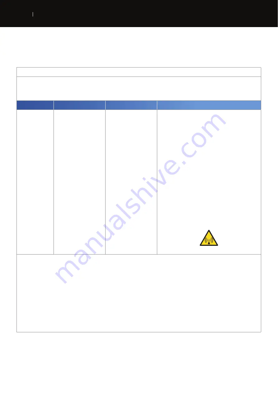
ELECTROMAGNETIC COMPATIBILITY (EMC) TABLES (CONTINUED)

Guidance and manufacturer’s declaration – electromagnetic immunity

The Intelect® Mobile 2 is intended for use in the electromagnetic environment specified below. 

The customer or the user of the Intelect® Mobile 2 should assure that it is used in such an electromagnetic environment.

IMMUNITY test 

IEC 60601 TEST LEVEL

Compliance level 

Electromagnetic environment – guidance

Conducted RF 
IEC 61000-4-6

Radiated RF 
IEC 61000-4-3

3 Vrms 
150 kHz to 80 MHz 
outside ISM bands

a


6 Vrms 
150 kHz to 80 MHz 
in ISM bands

a


10 V/m 
80 MHz to 2,5 GHz 
 
9-28V/m 
in wireless bands

3 Vrms 
 
6 Vrms 
 
10 V/m 
 
9-28V/m

Portable and mobile RF communications equipment should be used no closer 
to any part of the Intelect® Mobile 2, including cables, than the recommended 
separation distance calculated from the equation applicable to the frequency of 
the transmitter. 
Recommended separation distance
 
d = 1.2 √P 
 
d = 2 √P 
 
d = 1,2 √P 80 MHz to 800 MHz 
d = 2,3 √P 800 MHz to 2,5 GHz 
 
where P is the maximum output power rating of the transmitter in watts (W) 
according to the transmitter manufacturer and d is the recommended separation 
distance in metres (m).

b


Field strengths from fixed RF transmitters, as determined by an electromagnetic 
site survey,

c


should be less than the compliance level in each frequency range.

d


Interference may occur in the vicinity of equipment marked with the following 
symbol:

NOTE 1 At 80 MHz and 800 MHz, the higher frequency range applies.

NOTE 2 These guidelines may not apply in all situations. Electromagnetic propagation is affected by absorption and reflection from structures, objects and people.

a) The ISM (industrial, scientific and medical) bands between 150 kHz and 80 MHz are 6,765 MHz to 6,795 MHz; 13,553 MHz to 13,567 MHz; 26,957 MHz to 27,283 MHz; and 40,66 MHz to 40,70 
MHz. 
b) The compliance levels in the ISM frequency bands between 150 kHz and 80 MHz and in the frequency range 80 MHz to 2,5 GHz are intended to decrease the likelihood that mobile/portable 
communications equipment could cause interference if it is inadvertently brought into patient areas. For this reason, an additional factor of 10/3 has been incorporated into the formulae used in 
calculating the recommended separation distance for transmitters in these frequency ranges. 
c) Field strengths from fixed transmitters, such as base stations for radio (cellular/cordless) telephones and land mobile radios, amateur radio, AM and FM radio broadcast and TV broadcast cannot 
be predicted theoretically with accuracy. To assess the electromagnetic environment due to fixed RF transmitters, an electromagnetic site survey should be considered. If the measured field 
strength in the location in which the Intelect® Mobile 2 is used exceeds the applicable RF compliance level above, the Intelect® Mobile 2 should be observed to verify normal 
operation. If abnormal performance is observed, additional measures may be necessary, such as re-orienting or relocating the Intelect® Mobile 2. 
d) Over the frequency range 150 kHz to 80 MHz, field strengths should be less than 3 V/m


Summary of Contents for 15-1200

Page 1: ...EN...

Page 2: ...INTERFACE 9 VACUUM MODULE OPERATOR INTERFACE 10 INTELECT MOBILE 2 SET COMPONENTS 14 HEAD 14 LEADWIRES 14 POWERCORD 14 STIM SET INCLUDES 14 US SET INCLUDES 14 ULTRASOUND APPLICATOR 15 HEAD TO CART FIXA...

Page 3: ...SHORT CUTS 47 UNASSIGN SHORT CUT 49 CLINICAL RESOURCES 50 MODALITY WAVEFORM DESCRIPTIONS 53 TROUBLESHOOTING 55 GENERAL ACCESSORIES 56 BATTERY 56 ULTRASOUND APPLICATORS AND GEL 56 CLEANING THE INTELECT...

Page 4: ...he device is intended to be operated in the clinic and remote treatment locations The intended clinical conditions for use are a typical clinic setting including chiropractic clinics physical therapis...

Page 5: ...to previous screen Settings Indicates a USB Flash Drive is Inserted Indicates Battery Level Indicates more content can be viewed by swiping vertically Indicates more content can be viewed by swiping...

Page 6: ...y appear on the device Refer to Instructional Manual Booklet Warning Caution or Danger Electrical Type BF Equipment Ultrasound Play Pause ON OFF Manufacturer Date of manufacture Catalogue number Seria...

Page 7: ...Do not use over or applied to the eye Do not use over a pregnant uterus Tissue necrosis might result if the device is used on ischemic tissues in individuals with vascular disease where the blood supp...

Page 8: ...ipment is to be used only under the prescription and supervision of a licensed medical practitioner COMPONENTS Throughout these instructions the terms left and right referring to the machine sides are...

Page 9: ...and controls necessary for operator access to all operator utilities modalities and parameters for modi cation and system set up Color Display and touch screen 1 Adjustment dial 2 Play pause button 3...

Page 10: ...re or personal injury DO NOT permit foreign materials liquids or cleaning agents to enter the unit including but not limited to in ammables water and metallic objects to prevent unit damage malfuncti...

Page 11: ...y and if not installed and used in accordance with instructions for use may cause harmful interference to other devices in the vicinity Harmful interference to other devices can be determined by turni...

Page 12: ...use unit damage malfunction electrical shock re or personal injury Your unit was constructed to operate only on the electrical voltage speci ed on the Voltage Rating and Serial Number Plate Contact yo...

Page 13: ...er Cable 2m Black EU 15 0146 Wall Power Cable 2m Black UK 15 0147 Power Cable 2m Black AUS INTELECT MOBILE 2 SET COMPONENTS COMBO SET INCLUDES 15 0133 INTELECT MOBILE 2 COMBO 79967 Carbon electrodes 7...

Page 14: ...licator that makes contact with the patient during Ultrasound or Combination therapy 2 Applicator The assembly that connects to the system and incorporates the Applicator head 3 LED The component of t...

Page 15: ...ies and applicators used for the various modalities of the System The xation of the head to the cart is magnetic Remove the Intelect Mobile 2 device and cart from the shipping carton Visually inspect...

Page 16: ...DEVICE First time use always use mains power even if battery connected Insert the power cord into the back of the unit insert the plug into a power outlet do not position the Intelect Mobile 2 in suc...

Page 17: ...function on the Home Screen DEVICE WORKING ON BATTERY 1 Press the ON OFF button on the LCD Front panel as shown below 2 Select desired function on the Home Screen shown below ON OFF Button STOP TREAT...

Page 18: ...Right 2 Behaviour Steady when modality is selected and output is not active Flashing when output is active Quickly ashing when treatment is interrupted and user action is requested ON OFF BUTTON BLUE...

Page 19: ...96cm 10 1kg Device on cart 111 cm ULTRASOUND SPECIFICATIONS Frequency 1 MHz 3 MHz Duty Cycles 10 20 50 Continuous Pulse Repetition Rate 16 48 or 100 Hz Pulse duration 1 31 25 ms Max ON 31 25 ms Min OF...

Page 20: ...essure 50kPa to 106kPa Time required for the Intelect Mobile 2 to warm from the minimum storage temperature between uses until the Intelect Mobile 2 is ready for its INTENDED USE when the ambient temp...

Page 21: ...ssion in a circular motion The area treated should be Twice the diameter of the applicator For 5cm2 US applicator three times the diameter of the applicator if output power 4 W Continuous mode The app...

Page 22: ...EN DESCRIPTION 1 Menu Bar 2 Main Area 3 Channel Bar Each screen contains the following areas Menu Bar Located at the top of each screen and lists the current screen name Go to Home Screem Go to Previo...

Page 23: ...23 USER INTERFACE EN INTELECT MOBILE 2 ULTRASOUND USER MANUAL Main area Located under the menu bar this area displays icons unique to the current screen 1 Menu Bar 2 Main Area 3 Channel Bar...

Page 24: ...ound status box Stim Ch 1 status box Stim Ch 2 status box Intensity Remaining treatment time Treatment Progress Status Channel status possibilities Indicates the channel is available for use Indicates...

Page 25: ...just the display brightness select Brightness button The brightness range is 0 dimmest to 100 brightest in increments of 10 Default setting is 80 To adjust the volume of sound select the volume button...

Page 26: ...drive 3 in the setting menu eject the USB drive to enable safe removal from the Mobile 2 device 4 The format of the le is a bitmap le and it is date Time coded in the lename Note The print screen fun...

Page 27: ...ment Guidelines Save Overwrite default settings or Custom Protocols 1 Touch to activate 2 Adjust with Adjustment dial Clockwise Increase Counterclockwise Decrease Note When a parameter is not adjustab...

Page 28: ...following information Instructions for optimal US applicator use at the left side of the screen Images illustrating US treatment area and recommended applicator choice at the right side of the screen...

Page 29: ...s of Chattanooga Ultrasound Applicators will not work with the Intelect Mobile 2 2 From the home screen select the Ultrasound icon 3 SET UP TREATMENT On the treatment review screen you can adjust trea...

Page 30: ...30 USER INTERFACE EN INTELECT MOBILE 2 ULTRASOUND USER MANUAL 4 START TREATMENT Press the START button to begin the therapy 5 PAUSE TREATMENT Press the Start Pause button...

Page 31: ...ER MANUAL To resume treatment press the Start Pause button again Note Pause applies to the selected channel only 6 STOP TREATMENT First pause treatment by pressing the Start Pause button Then press th...

Page 32: ...from the Pause status When treatment has completed the Treatment Summary screen will appear with the following options Save the treatment protocol to the Custom Protocols cfr Page Assign to Assign the...

Page 33: ...e selected by the user and the suggested algorithm will select the parameter settings All settings can be edited to suit appropriate patient treatment prescription and patient comfort COMPLETE THE FOL...

Page 34: ...34 USER INTERFACE EN INTELECT MOBILE 2 ULTRASOUND USER MANUAL 3 Select INDICATION Touch to select Swipe vertically to see more 4 Select speci cation Touch to select...

Page 35: ...ettings are displayed and you can adjust parameters to desired level Refer to page for detailed description of the Treatment Review Screen Note Never start with intensity adjustment rst adjust all oth...

Page 36: ...36 USER INTERFACE EN INTELECT MOBILE 2 ULTRASOUND USER MANUAL 7 START TREATMENT Press the START button...

Page 37: ...nt data can be assigned to a folder at any time of the treatment set up running or completed but data will only be saved once the treatment is nished and channel is free for next treatment after press...

Page 38: ...38 USER INTERFACE EN INTELECT MOBILE 2 ULTRASOUND USER MANUAL SAVE TREATMENT DATA TO A NEW ID Enter ID and Save VIEW AND MANAGE TREATMENT DATA Press the TREATMENT DATA ICON on the home screen...

Page 39: ...2 ULTRASOUND USER MANUAL 1 VIEW Treatment Data Select desired ID folder The TREATMENT HISTORY is displayed including all previously saved treatment sessions ranked chronologically Select session to vi...

Page 40: ...40 USER INTERFACE EN INTELECT MOBILE 2 ULTRASOUND USER MANUAL 2 DELETE Treatment Data Delete all IDs Delete one ID...

Page 41: ...41 USER INTERFACE EN INTELECT MOBILE 2 ULTRASOUND USER MANUAL Delete all treatment sessions Delete one session...

Page 42: ...tom protocols to be de ned SAVE A CUSTOMIZED PROTOCOL A new custom protocol may be saved at any time using SAVE button 1 Touch SAVE on the TREATMENT REVIEW or TREATMENT SUMMARY screen 2 Select SAVE TO...

Page 43: ...library is displayed where you can save the protocol as NEW custom protocol or OVERWRITE an existing custom protocol Select and overwrite existing protocol Create new custom protocol Alphabetical lis...

Page 44: ...44 USER INTERFACE EN INTELECT MOBILE 2 ULTRASOUND USER MANUAL VIEW AND MANAGE CUSTOM PROTOCOLS Touch the CUSTOM PROTOCOLS icon on the Home Screen 1 VIEW Custom Protocol Select desired Custom Protocol...

Page 45: ...E 2 ULTRASOUND USER MANUAL The TREATMENT REVIEW SCREEN is displayed showing the protocol settings Start treatment or perform other actions as described in the Ultrasound Operations section 2 DELETE cu...

Page 46: ...custom protocol shortcut assignments on the home screen ASSIGN SHORTCUT Complete the following steps to assign a home screen shortcut Unassigned Shortcut icons appear grey in colour Press one of the...

Page 47: ...47 USER INTERFACE EN INTELECT MOBILE 2 ULTRASOUND USER MANUAL Shortcut assigned on Home screen Once assigned the shortcut icon becomes the colour associated with the modality it contains...

Page 48: ...l From the Home screen press and hold the shortcut icon you wish to unassign The unit will display a text box asking Remove My Custom Protocol 1 shortcut Select No to quit the unassignment process and...

Page 49: ...o use with the patient The modality and waveform descriptions provide information about the physical background and physiological effects of the different electrotherapy waveforms and ultrasound thera...

Page 50: ...ANUAL 2 Touch the body part for which you wish to view information Choose either anterior on left of screen or posterior on right of screen 3 The available images for the selected body part are displa...

Page 51: ...51 USER INTERFACE EN INTELECT MOBILE 2 ULTRASOUND USER MANUAL 4 Full screen image Close full screen mode...

Page 52: ...L MODALITY WAVEFORM DESCRIPTIONS Complete the following steps to view the ultrasound or waveform descriptions 1 Press the Ultrasound description icon on the Clinical Resources screen 2 Select the desi...

Page 53: ...53 USER INTERFACE EN INTELECT MOBILE 2 ULTRASOUND USER MANUAL 3 The modality or waveform description is displayed...

Page 54: ...MANUAL TROUBLESHOOTING 1 All system messages warning messages and fault messages that are generated by the device are self explanatory excepting system error 2 If System error occurs note error code a...

Page 55: ...1136 Mobile 2 Cart BATTERY Not available at launch Model Number Description 14 1086 Battery ULTRASOUND APPLICATORS AND GEL Model Number Description 15 0140 G16 Ultrasound Applicator 1 cm2 15 0141 G16...

Page 56: ...ld be performed daily Do not submerge the system in liquids Should the unit accidentally become submerged contact the dealer or DJO Service Department immediately Cleaning the LCD Screen Clean the LCD...

Page 57: ...obile 2 product tab 3 Complete the registration form to be informed about new product software version availability and IFU updates if not already done before 4 Go to documents tab 5 Click on the late...

Page 58: ...relieve the manufacturer of its liability and responsibility for safe system operation This will automatically void the warranty even before the end of the warranty period The warranty period for acc...

Page 59: ...ions CISPR 11 Group 1 The Intelect Mobile 2 uses RF energy only for its internal function Additionally the Intelect Mobile 2 contains a Bluetooth radio module Therefore its RF emissions are very low a...

Page 60: ...t 50 relative humidity Floors should be wood concrete or ceramic tile If oors are covered with synthetic material DJO recommends implementing additional controls to maintain relative humidity to at le...

Page 61: ...ymbol NOTE 1 At 80 MHz and 800 MHz the higher frequency range applies NOTE 2 These guidelines may not apply in all situations Electromagnetic propagation is affected by absorption and re ection from s...

Page 62: ...6 3 3 8 7 3 100 12 20 12 23 For transmitters rated at a maximum output power not listed above the recommended separation distance d in metres m can be determined using the equation applicable to the...

Page 63: ...ion Street Vista CA 92081 8553 U S A www DJOglobal com DJO France SAS Centre Europ en de Fr t 3 rue de Bethar 64990 Mouguerre France T 33 0 5 59 52 86 90 F 33 0 5 59 52 86 91 DJOglobal com 09 2019 DJO...

Reviews: