5
Ergostyle ™ FX Tables
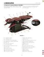
The nomenclature graphics below, Figure 2.1, indicate
the general locations of the major components of the
Ergostyle FX Table.
Know the components and their functions before
performing any operation of or service to the
Ergostyle FX Table.
FIGURE 2.1
1
2 NOMENCLATURE
2.1 ERGOSTYLE FX TABLE EXTERNAL COMPONENTS
Adjustable Ankle Rest
Ankle Release Lever
Autococking Controls (if applicable)
Autoflexion User Interface (if applicable)
Flexion Lock
Pelvic Drop Cocking Lever
Lateral Flexion Lever
Power Supply/Control Board Housing
Foot Control
Fixed Glide Levelers
Lumbar Drop Cocking Lever
Thoracic Drop Cocking Lever
Lower Frame Assembly
1.
2.
3.
4.
5.
6.
7.
8.
9.
10.
11.
12.
13.
Adjustable Glide Leveler
Safety Covers
Forward/Toggle Drop Tension Control
Forward Drop Cocking Lever
Head Cushion Width Adjustment
Head Cushion
Chest Section
Thoracic Drop Tension Knob
Breakaway/Elevating Chest Release
Lumbar Drop Tension Knob
Pelvic Section
T-Bar Assembly
Patient Switch Receptacle
14.
15.
16.
17.
18.
19.
20.
21.
22.
23.
24.
25.
26.
2
3
4
5
9
10
11
14
16
17
18
19
15
20
21
22
6
12
13
23
24
25
7
8
26
Summary of Contents for ERGOSTYLE FX 5820
Page 24: ...Ergostyle FXTables 22 8 SCHEMATICS Block Diagram 1 of 1 ...
Page 25: ...Ergostyle FXTables 23 8 SCHEMATICS Pneumatic 1 of 1 ...
Page 26: ...Ergostyle FXTables 24 8 SCHEMATICS Driver Board 58432 1 of 1 ...
Page 27: ...Ergostyle FXTables 25 8 SCHEMATICS Control Board 58433 1 of 1 ...
Page 28: ...Ergostyle FXTables 26 8 SCHEMATICS Daughter Board 58543 1 of 1 ...


