15
Ergostyle ™ FX Tables
5 REMOVAL & REPLACEMENT
5.5 MOTOR REMOVAL AND REPLACEMENT
Unplug the unit from the power source before
attempting removal or replacement procedures to
prevent electrical shock.
A. Part Numbers
Motor
. . . . . . . . . . . . . . . . . . . . . . . . . . . . . . . . . .58366
B. Equipment Required
#2 Phillips Screwdriver
3/16" Allen Wrench
1/2" End Wrench
C. Motor Removal
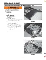
1.
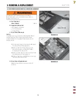
Position the Flexion end of the table in
the Up position as shown in Figure 5.11
to remove all possible tension from the
spring
mechanism.
2.
Raise or remove the cushion to allow access
to the motor mounting hardware.
3.
Remove the four Power Supply Cover
Mounting Screws with the #2 Phillips
Screwdriver. See Figure 5.12.
4.
Disconnect the Motor Connector from
the Driver Board Tension Connector. See
Figure
5.13.
5.
Remove Motor Cable from the
Power Supply Cover. Keep grommet
for
re-installation.
•
•
•
FIGURE 5.11
FIGURE 5.12
FIGURE 5.13
RAISE UP AND LOCK
INTO POSITION
POWER SUPPLY COVER
TENSION CONNECTOR
Summary of Contents for ERGOSTYLE FX 5820
Page 24: ...Ergostyle FXTables 22 8 SCHEMATICS Block Diagram 1 of 1 ...
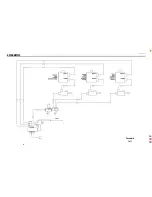
Page 25: ...Ergostyle FXTables 23 8 SCHEMATICS Pneumatic 1 of 1 ...
Page 26: ...Ergostyle FXTables 24 8 SCHEMATICS Driver Board 58432 1 of 1 ...
Page 27: ...Ergostyle FXTables 25 8 SCHEMATICS Control Board 58433 1 of 1 ...
Page 28: ...Ergostyle FXTables 26 8 SCHEMATICS Daughter Board 58543 1 of 1 ...


