


8
NORSE Operating Manual & Parts List 9681310 & 9681311
urn the pointer from the middle OFF position to the left
T
3.
urn the pointer from the middle OFF position to the left
urn the pointer from the middle OFF position to the left
Setting the miter tool to a 90º right angle
Setting the miter tool to a 90º right angle
g
It is recommended that you sand your workpiece with the disc
Setting the
hand or knee.
position, or push the emergency stop button with either your
o stop the machine, turn the pointer back the middle OFF
T
To stop the machine, turn the pointer back the middle OFF
5.
direction.
The right REV position will rotate the disc in the clockwise
4.
motion.
FOR position, and the disc will spin in the counter-clockwise
g
It is recommended that you sand your workpiece with the disc
e guards for forward or reverse rotation
hand or knee.
position, or push the emergency stop button with either your
o stop the machine, turn the pointer back the middle OFF
direction.
The right REV position will rotate the disc in the clockwise
FOR position, and the disc will spin in the counter-clockwise
urn the pointer from the middle OFF position to the left
It is recommended that you sand your workpiece with the disc
verse rotation
position, or push the emergency stop button with either your
o stop the machine, turn the pointer back the middle OFF
The right REV position will rotate the disc in the clockwise
FOR position, and the disc will spin in the counter-clockwise
g
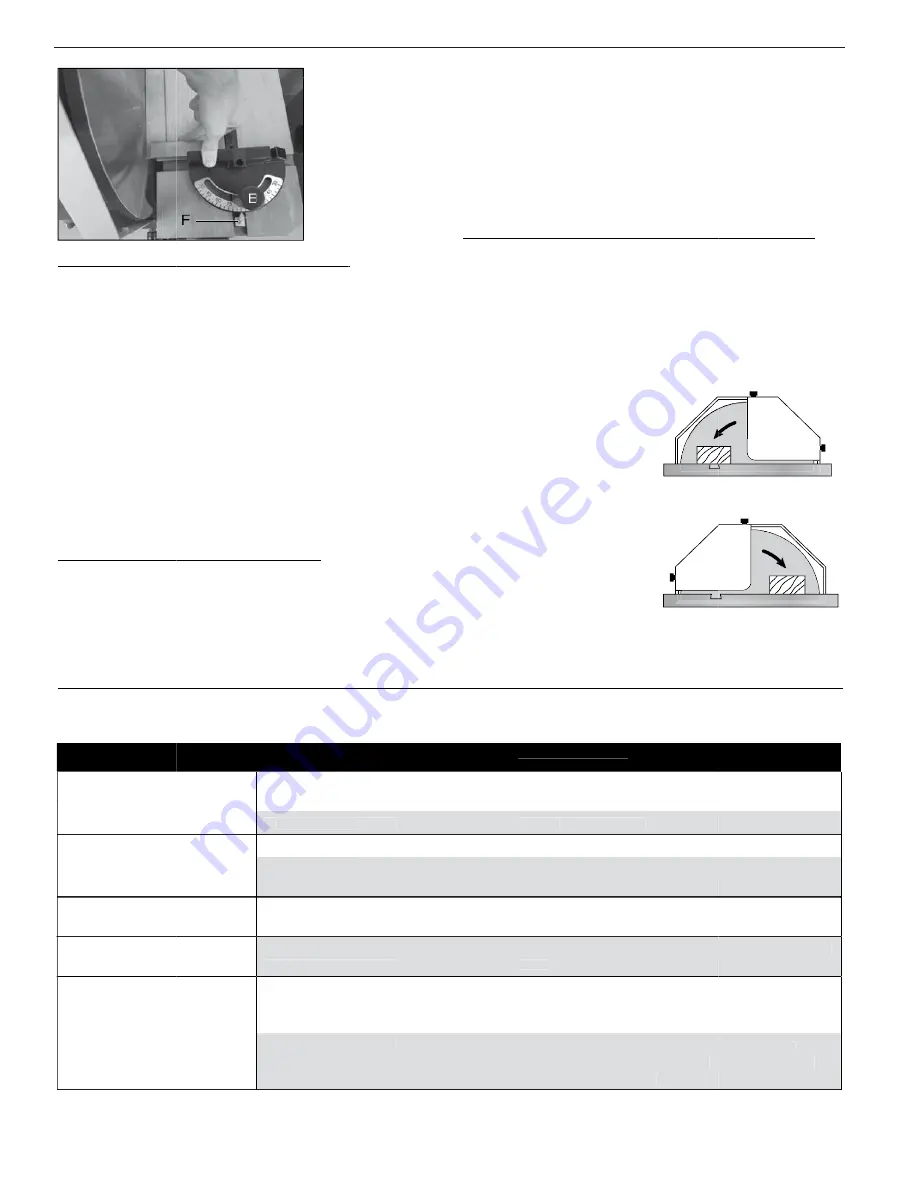
Use a machinist square or suitable tool and adjust the face
2.
Slightly loosen the miter tool adjustment push knob (E).
1.
tool while the abrasive sanding disc is removed.
While not required, it is much easier to adjust the miter
NOTE:
steps:
o set a true 90º refe
T
To set a true 90º reference for miter tool, perform the following
performs accurate flush and angled miter sanding operations.
The miter tool can be adjusted to ensure your disc sander
Setting the miter
g
g
Use a machinist square or suitable tool and adjust the face
Slightly loosen the miter tool adjustment push knob (E).
tool while the abrasive sanding disc is removed.
While not required, it is much easier to adjust the miter
o set a true 90º reference for miter tool, perform the following
performs accurate flush and angled miter sanding operations.
The miter tool can be adjusted to ensure your disc sander
r tool to a 90º right angle
Use a machinist square or suitable tool and adjust the face
Slightly loosen the miter tool adjustment push knob (E).
While not required, it is much easier to adjust the miter
o set a true 90º reference for miter tool, perform the following
performs accurate flush and angled miter sanding operations.
The miter tool can be adjusted to ensure your disc sander
according to the rotation of the sanding disc.
depending on the guard’
and removing the two black knobs on the top and back (or front
rear half of the sanding disc. Move the top guard by loosening
The top disc guard can be moved to expose either the front or
rotating down toward the workpiece to hold it against the table.
It is recommended that you sand your workpiece with the disc
o set up the machine for
T
To set up the machine for
rotation set up
Counterclockwise
according to the rotation of the sanding disc.
The guard’
s set up).
depending on the guard’
and removing the two black knobs on the top and back (or front
rear half of the sanding disc. Move the top guard by loosening
The top disc guard can be moved to expose either the front or
rotating down toward the workpiece to hold it against the table.
It is recommended that you sand your workpiece with the disc
o set up the machine for
rotation set up
Counterclockwise
Front
Machine
s position is set
The guard’
and removing the two black knobs on the top and back (or front
rear half of the sanding disc. Move the top guard by loosening
The top disc guard can be moved to expose either the front or
rotating down toward the workpiece to hold it against the table.
It is recommended that you sand your workpiece with the disc
g
out.
, and the emergency stop button is pulled
electrical supply
Ensure the machine is properly connected to a suitable
1.
Turning on the sa
Adjust the indicator pointer (F) to 90º if required.
4.
miter tool to ensure it is square.
Carefully tighten the adjustment push knob and recheck the
3.
tool face and flywheel disc.
of the miter tool until the square rests flush on both the miter
g
, and the emergency stop button is pulled
Ensure the machine is properly connected to a suitable
anding disc machine
Adjust the indicator pointer (F) to 90º if required.
miter tool to ensure it is square.
Carefully tighten the adjustment push knob and recheck the
tool face and flywheel disc.
of the miter tool until the square rests flush on both the miter
, and the emergency stop button is pulled
Ensure the machine is properly connected to a suitable
Adjust the indicator pointer (F) to 90º if required.
Carefully tighten the adjustment push knob and recheck the
of the miter tool until the square rests flush on both the miter
portion of the disc.
set the disc guard to the back
counterclockwise rotation,
o set up the machine for
T
To set up the machine for
the back portion of the disc.
guard to the front and sand on
clockwise rotation set the disc
o set up the machine for
T
To set up the machine for
Clockwise rotation set up
portion of the disc.
set the disc guard to the back
counterclockwise rotation,
o set up the machine for
Front
Machine
the back portion of the disc.
guard to the front and sand on
clockwise rotation set the disc
o set up the machine for
Clockwise rotation set up
emergency stop button.
Locate the power and direction switch to the left of the
2.
TROUBLESHOOTING GUIDE
Symptom
Sanding paper becomes glazed.
emergency stop button.
Locate the power and direction switch to the left of the
TROUBLESHOOTING GUIDE
Possible Cause(s)
Sanding paper becomes glazed. Sanding a painted or coated surface.
Locate the power and direction switch to the left of the
Corrective Action
grit.
Use open-end grain/flint sanding paper with a coarser
Sanding a painted or coated surface.
Possible Cause(s)
Corrective Action
Use open-end grain/flint sanding paper with a coarser
Use open-end grain/flint sanding paper with a coarser
orkpiece pulled fro
W
Workpiece pulled from hand.
.
quickly
Sanding paper burns, or clogs
Burn marks on workpiece.
orkpiece pulled from hand.
Allow the disc to cut freely
hand sand workpieces.
No support for workpiece. Do not free
disc.
Sanding paper burns, or clogs
disc.
Do not force the workpiece into sanding
rong sanding paper surface.
Burn marks on workpiece.
Forcing the workpiece into the sanding
ood is wet or g
W
W
Wood is wet or gummy
amounts of material in one pass.
table.
Use miter gauge. Keep workpiece firmly down against
hand sand workpieces.
No support for workpiece. Do not free
the disc to cut freely
Make several passes instead of trying to remove large
.
Allow the disc to cut freely
Do not force the workpiece into sanding
Use coarser grit for stock removal.
Do not force the workpiece into sanding disc.
Forcing the workpiece into the sanding
Use dif
rong sanding paper surface.
grit.
.
ood is wet or gummy
amounts of material in one pass.
table.
Use miter gauge. Keep workpiece firmly down against
.
Make several passes instead of trying to remove large
Use coarser grit for stock removal.
the disc to cut freely
Do not force the workpiece into sanding disc.
ferent material.
grit.
e dif
fferent material.
Make several passes instead of trying to remove large
Use miter gauge. Keep workpiece firmly down against
Allow
Do not force the workpiece into sanding disc.
8
Sanded edge is not square.
Sanded edge is not square.
sanding is not recommended.
able scale inacc
T
Table scale inaccurate.
Result of freehand sanding. Free hand
workpiece is square with sanding disc.
table angle if necessary
square. It should be 90 degrees.
Check table alignment to disc with a machinist’
able scale inaccurate.
square edge is desired. Use miter gauge to ensure
Keep workpiece flat on table at all times when a
sanding is not recommended.
Result of freehand sanding. Free hand
workpiece is square with sanding disc.
.
table angle if necessary
Adjust pointer and
square. It should be 90 degrees.
Check table alignment to disc with a machinist’
square edge is desired. Use miter gauge to ensure
Keep workpiece flat on table at all times when a
workpiece is square with sanding disc.
Adjust pointer and
s
Check table alignment to disc with a machinist’
square edge is desired. Use miter gauge to ensure
Keep workpiece flat on table at all times when a


