7
NORSE Operating Manual & Parts List 9681310 & 9681311
Table parallel alignment to disc
Table parallel alignment to disc
p
Table parallel alignment to disc
g
lel alignment to disc
v
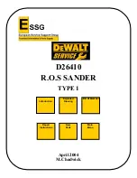
Remove the lower guard.
remove the four hex bolts (C) holding on the lower guard.
Use the supplied 4 mm hex wrench attached to the base to
3.
Remove the lower guard.
remove the four hex bolts (C) holding on the lower guard.
Use the supplied 4 mm hex wrench attached to the base to
remove the four hex bolts (C) holding on the lower guard.
Use the supplied 4 mm hex wrench attached to the base to
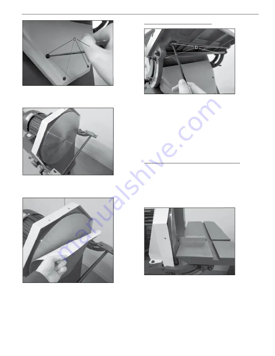
table can move.
Loosen the four bolts under the miter brackets enough so the
1.
o set the table gap perform the following steps:
T
To set the table gap perform the following steps:
touch the sanding disc and has a clearance gap of 1/16” or less.
disc to ensure flush sanding.
The workpiece table must be properly aligned to the sanding
table can move.
Loosen the four bolts under the miter brackets enough so the
o set the table gap perform the following steps:
touch the sanding disc and has a clearance gap of 1/16” or less.
The table must be set to it does not
disc to ensure flush sanding.
The workpiece table must be properly aligned to the sanding
Loosen the four bolts under the miter brackets enough so the
o set the table gap perform the following steps:
touch the sanding disc and has a clearance gap of 1/16” or less.
The table must be set to it does not
The workpiece table must be properly aligned to the sanding
Remove the sanding disc from the flywheel disc.
3.
Remove the sanding disc from the flywheel disc.
g
following steps:
o set a true 90º reference for your disc sander perform the
T
To set a true 90º reference for your disc sander perform the
performs accurate flush and angled miter sanding operations.
The workpiece table can be adjusted to ensure your disc sander
Setting the
during the process.
ighten the four bolts making sure the table does not move
T
3.
consistently 1/16” or less from front to back.
Align the table so the gap between the disc and table is
2.
g
following steps:
o set a true 90º reference for your disc sander perform the
performs accurate flush and angled miter sanding operations.
The workpiece table can be adjusted to ensure your disc sander
miter bracket to a 90º right angle
during the process.
ighten the four bolts making sure the table does not move
consistently 1/16” or less from front to back.
Align the table so the gap between the disc and table is
g
o set a true 90º reference for your disc sander perform the
performs accurate flush and angled miter sanding operations.
The workpiece table can be adjusted to ensure your disc sander
ht angle
ighten the four bolts making sure the table does not move
consistently 1/16” or less from front to back.
Align the table so the gap between the disc and table is
grease.
Clean the flywheel disc of any left-over adhesive, dirt or
4.
Clean the flywheel disc of any left-over adhesive, dirt or
Clean the flywheel disc of any left-over adhesive, dirt or
removed.
alignment adjustments while the abrasive sanding disc is
While not required, it is much easier to make table
NOTE:
following steps:
alignment adjustments while the abrasive sanding disc is
While not required, it is much easier to make table
alignment adjustments while the abrasive sanding disc is
While not required, it is much easier to make table
Aligning the bottom of the disc and adhere
sanding disc.
Remove the adhesive backing from the top half of the
5.
Aligning the bottom of the disc and adhere
Remove the adhesive backing from the top half of the
Aligning the bottom of the disc and adhere
Remove the adhesive backing from the top half of the
Use a machinist square or suitable tool and adjust the table
2.
the workpiece table so it can move.
Slightly loosen the miter adjustment levers on both ends of
1.
Use a machinist square or suitable tool and adjust the table
the workpiece table so it can move.
Slightly loosen the miter adjustment levers on both ends of
Use a machinist square or suitable tool and adjust the table
Slightly loosen the miter adjustment levers on both ends of
Replace the lower guard, table and upper guard.
7.
ensure it is tightly adhered to the flywheel disc.
After the new abrasive disc is attached, press firmly on it to
6
the abrasive sanding disc on the flywheel disc.
adhere the bottom of the sanding disc.
Then remove the bottom adhesive backing and
the top first.
Aligning the bottom of the disc and adhere
sanding disc.
Replace the lower guard, table and upper guard.
ensure it is tightly adhered to the flywheel disc.
After the new abrasive disc is attached, press firmly on it to
the abrasive sanding disc on the flywheel disc.
ake care
T
Take care to center
adhere the bottom of the sanding disc.
Then remove the bottom adhesive backing and
Aligning the bottom of the disc and adhere
After the new abrasive disc is attached, press firmly on it to
ake care to center
Then remove the bottom adhesive backing and
Aligning the bottom of the disc and adhere
Adjust the indicator pointer to 90º if required.
4.
Carefully tighten the adjustment lever and recheck the table.
3.
until the square rests flush on both the table and disc.
Use a machinist square or suitable tool and adjust the table
2.
Adjust the indicator pointer to 90º if required.
Carefully tighten the adjustment lever and recheck the table.
until the square rests flush on both the table and disc.
Use a machinist square or suitable tool and adjust the table
7
Adjust the indicator pointer to 90º if required.
Carefully tighten the adjustment lever and recheck the table.
until the square rests flush on both the table and disc.
Use a machinist square or suitable tool and adjust the table