69
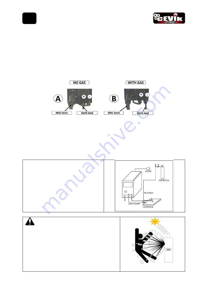
8.1.4.3 Connect Torch Connection Power Lead (7) to the positive (+) welding output terminal (6)
8.1.4.4 Connect Earth Lead Quick Connector (22) to the negative (-) output welding terminal (8). See picture
B.
8.1.4.5 Connect Earth Clamp (22) to the work piece. Contact with workpiece must be strong contact with
clean, bare metal, with no corrosion, paint or scale at the contact point.
8.1.4.6 Connect the gas regulator (optional) and gas line to the inlet on the rear panel (9). If the regulator is
equipped with a flow gauge, the flow should be set between 8 – 15 L/minute depending on application. If gas
regulator is not equipped with a flow gauge, adjust pressure so gas can just be heard coming out of the torch
conical nozzle (24). It is recommended that gas flow is checked again, just prior to starting weld This can be
done by triggering the MIG torch with the unit powered up.
8.1.5.
Configuration for the TIG welding process with GAS PROTECTION.
8.1.5.1 The TIG torch power cable (not included) is connected to the negative welding terminal.
8.1.5.2 The gas tube is connected to the gas bottle regulator.
8.1.5.3 Then open the gas bottle valve and the gas regulator valve. We can control the gas flow by
regulating from the valve in the TIG torch.
8.1.5.4 Have the tungsten tip touch the work piece, raise the TIG torch little by little, until you see that
the arc remains stable. You can start welding.
8.1.6
Connection of Shield Gas
.
Connect the gas tube of the bottle outlet
regulator to the equipment inlet connector (9). Be
sure to make all connections firmly to avoid gas
leaks and thus be able to start welding in a
protected manner.
WARNING!!!.
Please keep in mind:
1.
Protective gas leak affects welding performance.
2.
Avoid exposing the gas bottle to the direct action of
the sun's rays and thus avoid a possible explosion of
the bottle due to the increasing pressure of the gas
caused by heat.
ES


