


Base Unit Manual
2019 Cervis, Inc.
5
3.1
BU-x18XF/BU-xH18XF Base Unit Installation
Caution!
During installation, disable the machine on which the base unit will
be installed.
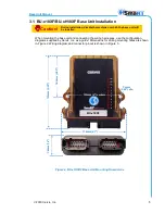
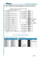
When mounting the base unit and connecting the wiring harnesses, use the configuration
diagrams supplied by Cervis, Inc. as a guide. Dimensions for drilling mounting holes are shown
in Figure 2. Wiring diagram and connector pinout is shown in Figure 3.
Figure 2. BU-xH18XF Base Unit Mounting Dimensions
102mm (4") centers
7.4mm
(0.29") dia.
13
3m
m
(5
.2
5
"
)
7
4
.9
m
m
(2
.9
5
"
)
118mm (4.7")
36
mm
(
1.
4
"
)
BU-x18XF


