


Base Unit Manual
2019 Cervis, Inc.
3
2.0
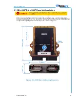
BU-x18XF Base Unit
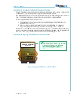
Figure 1. SmaRT BU-x18XF/BU-xH18XF Base Unit
The versatile BU-x18XF and BU-xH18XF base units
—where x=2 for 2.4GHz, or 9 for 900MHz
operation
—feature 18 FET (field effect transistor) high-side switching outputs or switch-to-
ground digital inputs, factory configurable dual 0
–10VDC or 0–20mA analog inputs that can also
be configured as digital outputs/inputs, and Control Area Network (CAN) Bus control capability.
Eight pairs of base unit FET channels can be equipped with high-side current sense for better
valve coil pair control. Table 1 on page 4 lists available configurations and options.
The BU-x18XF and BU-xH18XF accept a broad range of input power, with operating voltages
ranging from 7VDC to 28VDC. The rugged, weatherproof translucent enclosure allows these
units to operate worry-free in harsh weather conditions. Color-keyed or wire-numbered
weatherproof cable harnesses connect the controlled devices. These base units create a robust
communications link with up to eight SmaRT remote control units in congested radio
environments using Direct Sequence Spread Spectrum (DSSS) wireless technology. Base units
and remote control units feature seamless association without the need to open the enclosures.
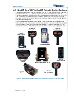
There is a variety of available SmaRT remote control units to choose from, multiple examples of
which are shown in Figure 4.
Features
18 solid-state FET outputs/inputs
Two 0
–10V or 4–20mA inputs, or digital input/outputs (factory configurable)
900MHz or 2.4GHz Direct Sequence Spread Spectrum technology
Dual uniquely keyed connectors for ease of wiring
Diagnostic LEDs
+7 to +28VDC power
Compact design
Rugged, weatherproof construction
Communicates with up to eight SmaRT remotes
Optional RS-232 models for
SmaRT Connect
use (see Table 1, Figure 3, or Table 2)


