11
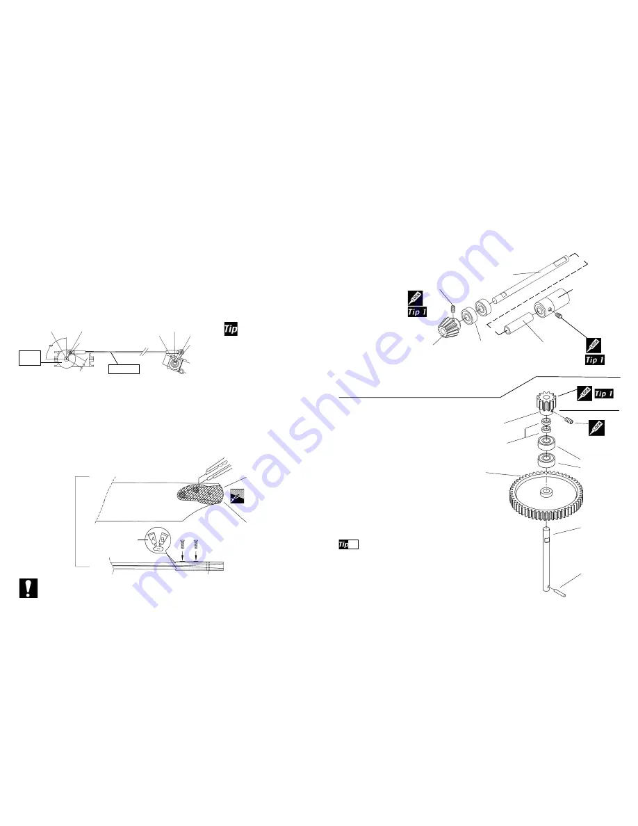
Step 11B Torque Drive Pinion Gear
From parts bag 2: Using threadlock, insert one M3x4
Set Screw (
Tip 1
) into the gear, note where the
flat spot is on the shaft and
slide the gear on and
tighten (
make sure
the set screw is
positioned over the
flat spot
) the set
screw. Slide two Ball
Bearings onto the shaft
and install into one half
of the upper frames.
Next add the spacer,
apply threadlock to the
M4x4 set screw and
insert into the torque
drive coupler. Slide the
drive coupler over the
long flat spot until the there is no end play in the shaft
and tighten the set screw in place.
From parts bag 2: Assemble the
engine drive gear assembly, start by
pressing the guide pin into the hole in
the end of the Drive Shaft. Insert the
shaft through the Counter Gear (
make sure the pin is fully seated
in the recessed side of the gear
)
then slide the two M5x13 Ball Bear-
ings.
R30
slide two M5x7x2 spacers
onto the shaft and slide the Alloy
Drive Gear onto the shaft aligning the
flat spot on the shaft. Insert one M3x4
set screw (Tip1) into the Alloy Drive Gear
and tighten in place.
Test fit the gear assembly into one half of the upper side
frames. While holding the pinion gear, try to slide the
counter gear up and down on the shaft. The gear should not slide up
the shaft, if it does, readjust the top pinion to remove the slop and re-
tighten the set screw using threadlock. It is important that there is no
free play but the bearings are turning freely when assembled. Apply a
small amount of red locktight to the top of the counter shaft and insert
into the pinion gear.(not the set screw).
Step 12 Counter Gear Assembly
5x13 Ball Bear-
ings x 2
[CNBB1350]
Tail Transmission
Output Shaft
[HW3059A]
Tail Rotor
Output Gear
[HW3057]
M3x4 Set Screw
(small hex key)
Output Shaft
Spacer
[HW3059A]
Torque Drive
Coupler
[HI3154]
M4x4 Set Screw
(med hex key)
1
Alloy Drive Gear 13T
(
R30
) [HW3045]
M5x7x2 Spacer x 2
(
SE30
)
Counter Gear
55T (
SE30
)
[HI3040]
5x13 Ball
Bearings x 2
[CNBB1350]
M2x12 Pin
[HI3040]
Drive Shaft
[HW3042]
M3x4 Set Screw (
30
)
From Bag 4: Attach one steel ball and one 2mm nut, to both the Throttle servo horn and the Throttle
Extension from Step 18 using threadlock. Position the ball at 10mm from the center of the servo and in
the outermost hole on the metal throttle arm. With the radio on, and the throttle stick centered and the
trim in the center, press the servo horn onto the servo so the ball is at 90 degrees to the servo ( the hover-
ing position ). Move the throttle stick to the low/idle position and press the Throttle Pushrod (
B
) onto the
steel balls. Check that in the low position the carburetor has about a 1mm wide opening for idling and
finally as the trim is moved fully down the carburetor closes completely to shut the engine off. Also check
that in the high position the carburetor is fully open. The throttle extension nut may have to be loosened
and the lever repositioned to operate as recommended
.
Shut Down
- Trim full down
Full Power
Open 100%
Hover-Carb open
50%
0% Idle
- Trim at Middle
Hover
50%
100% Full
Power
Idle-Carb open
aprox. 1mm
Carb closed
Throttle
Servo
Pushrod B
Step 44 Throttle Linkage
Pushrod B will vary in
length slightly as the
position of the carburetor is
different for each engine
manufacturer. Following the
above instructions will allow
you to get the carburetor
setup correctly.
Step 45A Aerotech Main Blade Assembly - Raven 30
The Main Rotor Blades in the Raven 30 kit are pre-built and balanced, the only work required is to glue the
blade grip root ends to the blades (
Please note that this step is necessary to insure the blades will not sepa-
rate from the helicopter during flight!!
). Temporarily install the root ends ( see note ) onto the blades by
cutting the covering over the holes and using a pencil, mark the outline of the plastic parts on the covering.
Remove the root ends and mark a second line about 3mm inside the first and trim away this inside portion of the
covering with a sharp hobby knife. Using some sandpaper roughen the plastic root ends and glue them in place
with Slow CA or slow Epoxy glue. Install the blades onto the rotorhead to dry. This will ensure the thickness is
correct when finished.
Note: The plastic root ends have a top and bottom which are different when viewed from the
large end.
Test fit the parts to be sure that the total thickness of the blades is 12mm. The 3mm
brass tube and four M4x20 flat washers are not needed on the helicopter.
R-30
Sand both the
plastic root ends
Cut away
this portion
of the
covering
in the shape
of the blade
root.
HW3190
(Main blade set)
Trailing Edge
of Blade
Leading Edge
of Blade
Use Slow CA
glue or Slow
Epoxy
R-30


