page 16
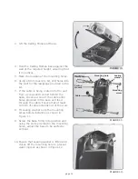
6. Use a 6mm drill bit to open the required
cable entry hole.
FIGURE 22.
Circuit
board
Power
cable
Cable
saddles
6mm drill bit
FIGURE 21.
Inserting an Activated
SIM Card
FIGURE 23.
Cable
entry
hole
1. Slide the SIM card housing’s locking
mechanism up to release the housing.
Ensure that the activated SIM card
going into the Module for the first
time is not PIN protected
Do not use a screwdriver to
open the SIM Card locking
mechanism.
7. Fix the cable to the wall using cable
saddles.
8. Seal all the holes with silicone sealant.
9. Re-insert the circuit board and ensure
that the retaining clips are holding it in
place
Ensure sufficient cable is provided
for to reach the terminals of both
the I/O terminals and the voice
communication terminals
Voice
communication
cable
Cover
Summary of Contents for G-SPEAK
Page 1: ...G SPEAK Installation Manual GSM BASED INTERCOM SYSTEMS TM...
Page 39: ......


