Central Machinery 66435 Set Up And Operating Instructions Manual Download Page 14

SKU 66435 

For technical questions, please call 1-800-444-3353. 

Page 14

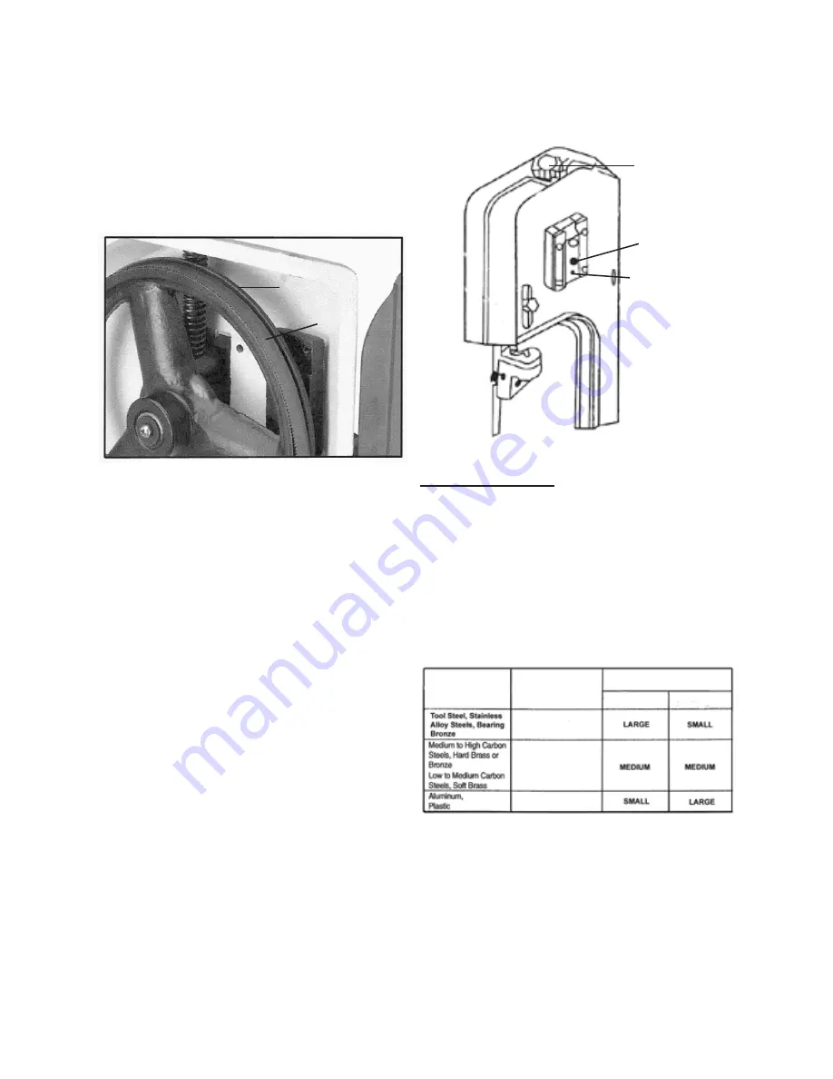
The Saw Blade (86) is tracking prop-

2. 

erly when the back of the Blade is 

just touching the edge of the Blade 

Wheel (64) flange.  The back of the 

Blade should not be rubbing against 

the flange.  

(See Figure j.)

BLADE WHEEL

FLANGE

(64)  SAW

BLADE

(86)

FIGUrE j

If adjustment is necessary, loosen the 

3. 

upper Hex Head Bolt (56) to a point 

where it is loose, but snug. 

(See Figure K.)

With the Bandsaw running, turn the 

4. 

lower Hex Head Screw (110) until the 

Saw Blade (86) is tracking properly, 

making sure Blade tension is main-

tained by turning the Blade Tension 

Adjusting Knob (125). 

(See Figure K.)

Make sure to retighten the upper Hex 

5. 

Head Screw (56) when adjustment is 

complete.  

(See Figure K.)


HEx HEAD

SCrEW

(56)

HEx HEAD

SCrEW

(110)

FIGUrE K

BLADE

TENSION

ADjUSTING

KNOB

(125)

Changing Speed:

When using the Bandsaw, always 

1. 

change the Saw Blade (86) speed to 

best suit the material being cut.  Refer 

to the Chart to determine the proper 

cutting speed for a specific type of 

material being cut.  

(See Figure L.)

FIGUrE L

MATErIAL

SpEED (FpM)

BELT GrOOVE USED

WOrM GEAr

pULLEY

MOTOr

pULLEY

80 FpM

120 FpM

180 FpM

The cutting speed can be adjusted by 

2. 

loosening the Screw (102) and mov-

ing the Motor (94) forward.  Open the 

Upper Pulley Cover (92).  Place the V-

Belt (128) around the desired grooves 

in the Worm Gear Pulley (115) and 

Summary of Contents for 66435

Page 1: ...Copyright 2008 by Harbor Freight Tools All rights reserved No portion of this manual or any artwork contained herein may be reproduced in any shape or form without the express written consent of Harbo...

Page 2: ...DS 8 SYMBOLOGY 9 SPECIFICATIONS 9 UNPACKING 9 ASSEMBLY INSTRUCTIONS 9 PRODUCT FEATURES 11 TOOL SET UP 12 WORKPIECE AND WORK AREA SET UP 16 OPERATING INSTRUCTIONS 16 MAINTENANCE AND SERVICING 20 REPLAC...

Page 3: ...rt symbol indicates a hazardous situation which if not avoided could result in minor or moderate injury NOTICE is used to address practices not related to personal injury CAUTION without the safety al...

Page 4: ...personal injury Use personal protective equip b ment Always wear eye protection Safety equipment such as dust mask non skid safety shoes hard hat or hearing protection used for appropri ate conditions...

Page 5: ...are easier to control Use the power tool and its acces g sories in accordance with these instructions taking into account the working conditions and the work to be performed Use of the power tool for...

Page 6: ...top if the Blade is to be backed out of an un completed cut Never attempt to remove material 18 stuck in the moving parts of the Band saw while it is plugged in and running Make sure the workpiece to...

Page 7: ...n 29 this product will expose you to lead a chemical known to the State of California to cause cancer and birth defects or other reproductive harm Wash hands after handling Califor nia Health Safety C...

Page 8: ...he applicable standards of Underwriters Labora tories Inc the Canadian Standard Association and the National Electri cal Code See Outlets for 2 Prong Plug Double insulated tools may be used 2 in eithe...

Page 9: ...min No Load Revolutions per Minute RPM Specifications Electrical Requirements 120 V 60 Hz 550 Watts 2 25 Amps No Load Motor Type Single Phase Fan Cooled Motor HP 1 3 Motor RPM 1725 Power Switch Type...

Page 10: ...ASHER 11 HEX NUT 7 To Attach The Floor Stand Handle To The Front Floor Stands Insert the Floor Stand Handle 1 into 1 the two Front Floor Stands 5 Then use two Cotter Pins 2 to secure the Floor Stand H...

Page 11: ...n place by tightening the Set Screw See Figure D FIGURE D STOCK STOP 29 STOCK STOP ROD 28 SET SCREW PRODUCT FEATURES Motor 94 1 Pulley Cover 92 2 Saw Blade 86 3 Blade Guide Adjustment Screw 67 4 Blade...

Page 12: ...nted to a Guide Pivot 72 74 and can be adjusted The inner Blade Guide Bearing is not adjustable See Figure F Loosen the Hex Nut 7 while hold ing the Guide Pivot 72 74 with a wrench See Figure F Use a...

Page 13: ...on Adjusting Knob counterclockwise to decrease tension on the Saw Blade Correct tension is acquired when the Saw Blade is just tight enough so that no slippage oc curs between the Saw Blade and the Bl...

Page 14: ...ned by turning the Blade Tension Adjusting Knob 125 See Figure K Make sure to retighten the upper Hex 5 Head Screw 56 when adjustment is complete See Figure K HEX HEAD SCREW 56 HEX HEAD SCREW 110 FIGU...

Page 15: ...PULLEY 93 Feed Rate Adjustment The feed rate of the Blade can be 1 adjusted by turning the Adjusting Rod 58 clockwise to decrease the feed rate or counterclockwise to increase the feed rate Do not tur...

Page 16: ...he work area without creating a tripping hazard or exposing the Cord to possible dam age The Cord must reach the work area with enough extra length to allow free movement while working Secure loose wo...

Page 17: ...s into the Body Frame See Figure S FIGURE S BODY FRAME 126 SUPPORT PLATE 31 Remove the two Cross Head Screws 4 87 from the Lower Blade Guard 9 See Figure T FIGURE T CROSS HEAD SCREWS 87 Attach the Ver...

Page 18: ...ch 20 up to its 9 ON position See Figure X Before cutting turn on the Bandsaw 10 and check for excessively loose Saw Blade 86 tension or machine vibra tion If this is found turn off the Band saw and c...

Page 19: ...ure its en tire length is properly supported If necessary use a roller stand not included with a larger workpiece If cutting several workpieces at the 5 same length you may wish to adjust the Stock St...

Page 20: ...anual must be performed only by a qualified technician To prevent serious injury from accidental operation Turn the Power Switch 20 of the Bandsaw to its OFF position and unplug the machine from its e...

Page 21: ...to be cut The thin ner the workpiece the more teeth is recommended A minimum of 3 teeth should engage the workpiece at all times for proper cutting CAU TION If the teeth of the Saw Blade are so far a...

Page 22: ...re an oil change more than once a year unless the oil becomes contaminated or a leak occurs due to improper replacement of the Gear Box Cover 109 Changing this oil should be done by a qualified servic...

Page 23: ...SKU 66435 For technical questions please call 1 800 444 3353 Page 23 TROUBLESHOOTING...

Page 24: ...SKU 66435 For technical questions please call 1 800 444 3353 Page 24 TROUBLESHOOTING CONTINUED Crooked...

Page 25: ...SKU 66435 For technical questions please call 1 800 444 3353 Page 25 PARTS LIST Description Qty Description Qty Idler Wheel Drive Wheel Pulley Tray Pulley Cover...

Page 26: ...he buyer that he or she is qualified to make any repairs to the product or that he or she is qualified to replace any parts of the product In fact the manufacturer and or distributor expressly states...

Page 27: ...SKU 66435 For technical questions please call 1 800 444 3353 Page 27 ASSEMBLY DIAGRAM...

Page 28: ...SKU 66435 For technical questions please call 1 800 444 3353 Page 28 ASSEMBLY DIAGRAM CONTINUED...

Page 29: ...low the exclusion or limitation of incidental or consequential damages so the above limitation of exclusion may not apply to you This warranty is expressly in lieu of all other warranties express or i...

Reviews: